Toyota 4Runner: Crawl Indicator Light does not Come ON
DESCRIPTION
If any of the following conditions are met, the crawl indicator light blinks and crawl control is stopped.
- Crawl control is operated when the vehicle stability control system is malfunctioning, or a vehicle stability control system malfunction occurs during crawl control.
- The transfer is shifted to H4 during crawl control.
- The shift lever is moved to P or N during crawl control.
- The driver door is opened during crawl control.
When the vehicle is driven at 25 km/h (16 mph) or more during crawl control, control is temporarily stopped and the crawl indicator light blinks.
When using crawl control continually for a long period of time, if the temperature inside the hydraulic brake booster becomes too high, the crawl indicator light will turn off after blinking. After a while, the temperature decreases and crawl control becomes operable.
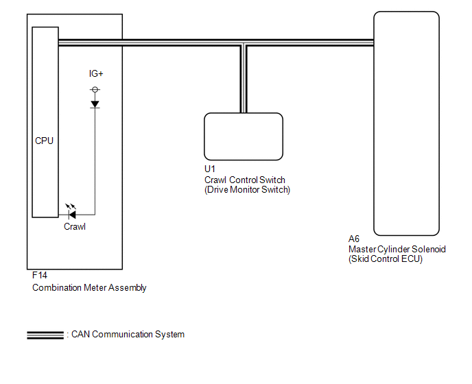
WIRING DIAGRAM
CAUTION / NOTICE / HINT
NOTICE:
When replacing the master cylinder solenoid, perform calibration (See page
.gif) ).
).
PROCEDURE
|
1. |
CHECK CAN COMMUNICATION LINE |
(a) Turn the ignition switch off.
(b) Connect the Techstream to the DLC3.
(c) Turn the ignition switch to ON.
(d) Turn the Techstream on.
(e) Select CAN Bus Check from the System Selection Menu screen and follow the
prompts on the screen to inspect the CAN bus (See page
).
OK:
CAN Bus Check indicates no malfunctions in CAN communication.
| NG | .gif) |
GO TO CAN COMMUNICATION SYSTEM (HOW TO PROCEED WITH TROUBLESHOOTING) |
|
.gif)
|
2. |
CHECK FOR DTC |
(a) Check for DTCs (See page ).
Result
|
Result |
Proceed to |
|---|---|
|
DTC is not output |
A |
|
DTC is output |
B |
| B | |
REPAIR CIRCUITS INDICATED BY OUTPUT DTCS |
|
|
3. |
READ VALUE USING TECHSTREAM (CRAWL CONTROL MAIN SWITCH) |
(a) Turn the ignition switch off.
(b) Connect the Techstream to the DLC3.
(c) Turn the ignition switch to ON.
(d) Turn the Techstream on.
(e) Enter the following menus: Body Electrical / D-SEAT SW / Data List.
D-SEAT SW|
Tester Display |
Measurement Item/Range |
Normal Condition |
Diagnostic Note |
|---|---|---|---|
|
Crawl Control Main Switch |
Crawl control switch/ ON or OFF |
ON: Crawl switch on OFF: Crawl switch off |
- |
OK:
The Techstream displays ON or OFF according to crawl control switch operation.
| NG | |
GO TO STEP 5 |
|
|
4. |
READ VALUE USING TECHSTREAM (CRAWL CONTROL LIGHT) |
(a) Turn the ignition switch off.
(b) Connect the Techstream to the DLC3.
(c) Turn the ignition switch to ON.
(d) Turn the Techstream on.
(e) Enter the following menus: Chassis / ABS/VSC/TRAC / Data List.
ABS/VSC/TRAC|
Tester Display |
Measurement Item/Range |
Normal Condition |
Diagnostic Note |
|---|---|---|---|
|
Crawl Control Light |
Crawl control indicator light/ ON or OFF |
ON: Indicator light on OFF: Indicator light off |
- |
(f) When performing the Crawl Control Light Active Test, check Crawl Control
Light in the Data List (See page ).
ABS/VSC/TRAC
|
Tester Display |
Test Part |
Control Range |
Diagnostic Note |
|---|---|---|---|
|
Crawl Control Light |
Crawl control indicator light |
Indicator light ON/OFF |
Observe the combination meter. |
|
Result |
Proceed to |
|
|---|---|---|
|
Data List Display |
Data List Display when Performing Active Test ON/OFF Operation |
|
|
ON |
Does not change between ON and OFF |
A |
|
Changes between ON and OFF |
B |
|
|
OFF |
Does not change between ON and OFF |
A |
|
Changes between ON and OFF |
B |
|
| A | |
REPLACE MASTER CYLINDER SOLENOID |
| B | |
GO TO METER / GAUGE SYSTEM (HOW TO PROCEED WITH TROUBLESHOOTING) |
|
5. |
CHECK TERMINAL VOLTAGE AND RESISTANCE (IG, +B, GND) |
| OK | |
REPLACE DRIVE MONITOR SWITCH |
| NG | |
REPAIR OR REPLACE HARNESS OR CONNECTOR |
 Crawl Indicator Light Remains ON
DESCRIPTION
Refer to Crawl Indicator Light does not Come ON (See page
).
WIRING DIAGRAM
Refer to Crawl Indicator Light does not Come ON (See page
).
CAUTION / NOTICE / HINT
NOTICE:
When repl ...
 Multi-terrain Select Indicator Light Remains ON
DESCRIPTION
Refer to Multi-terrain Select Indicator Light does not Come ON (See page
).
WIRING DIAGRAM
Refer to Multi-terrain Select Indicator Light does not Come ON (See page
).
PROCEDURE
...
Other materials about Toyota 4Runner:
Inspection
INSPECTION
PROCEDURE
1. INSPECT WIRELESS DOOR LOCK BUZZER
(a) Measure the resistance according to the value(s) in the table below.
HINT:
The buzzer activation circuit is built into the ECU, not into the buzzer
itself. When battery volta ...
Front Wiper Rubber
Components
COMPONENTS
ILLUSTRATION
Replacement
REPLACEMENT
CAUTION / NOTICE / HINT
HINT:
Use the same procedure for the RH and LH sides.
The procedure listed below is for the LH side.
PROCEDURE
1. REMOVE FRONT WIPER BLADE
(a) ...

0.0234