Toyota 4Runner: Removal
REMOVAL
CAUTION / NOTICE / HINT
CAUTION:
Wear protective gloves. Sharp areas on the parts may injure your hands.
PROCEDURE
1. REMOVE REAR NO. 1 SEAT ASSEMBLY LH
(a) Remove the rear No. 1 seat assembly LH (See page
.gif) ).
).
2. REMOVE REAR SEAT UPPER RECLINING COVER LH
3. REMOVE RECLINING ADJUSTER RELEASE HANDLE LH
4. REMOVE CENTER SEAT HINGE COVER RH
5. REMOVE REAR SEAT CUSHION MOULDING LH
6. REMOVE REAR SEATBACK LOCK STRIKER COVER LH
7. REMOVE SEAT CUSHION COVER WITH PAD
8. REMOVE CENTER SEATBACK ASSEMBLY
9. REMOVE REAR NO. 1 SEAT INNER BELT ASSEMBLY LH
10. REMOVE RECLINING ADJUSTER KNOB CAP LH
11. REMOVE REAR SEAT LOCK CONTROL LEVER SUB-ASSEMBLY LH
12. REMOVE SEAT BELT ANCHOR COVER CAP
13. REMOVE REAR SEAT SHOULDER BELT COVER
14. REMOVE REAR SEATBACK COVER
15. REMOVE REAR SEATBACK BOARD CARPET ASSEMBLY LH
16. REMOVE REAR NO. 1 SEAT HEADREST SUPPORT ASSEMBLY
17. REMOVE SEATBACK COVER WITH PAD
18. REMOVE REAR SEATBACK EDGE PROTECTOR
19. REMOVE REAR SEAT SHOULDER BELT GUIDE
20. REMOVE NO. 1 SEAT 3 POINT TYPE BELT ASSEMBLY LH
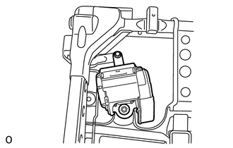
(a) Remove the nut and bolt, and then detach the 2 claws and remove the seat belt.
 Inspection
INSPECTION
PROCEDURE
1. INSPECT NO. 1 SEAT 3 POINT TYPE BELT ASSEMBLY LH
NOTICE:
Do not disassemble the retractor.
(a) When the inclination of the retractor is 15° or less, check that the belt ...
 Installation
INSTALLATION
CAUTION / NOTICE / HINT
CAUTION:
Wear protective gloves. Sharp areas on the parts may injure your hands.
HINT:
A bolt without a torque specification is shown in the standard bolt cha ...
Other materials about Toyota 4Runner:
Data List / Active Test
DATA LIST / ACTIVE TEST
1. DATA LIST
HINT:
Using the Techstream to read the Data List allows the values or states of switches,
sensors, actuators and other items to be read without removing any parts. This non-intrusive
inspection can be very useful bec ...
CD Sound Skips
PROCEDURE
1.
CHECK CD
(a) Check that the CD is not deformed or cracked.
OK:
No deformation or cracks on the CD
NG
CD IS FAULTY
...

0.0223