Toyota 4Runner: Removal
REMOVAL
CAUTION / NOTICE / HINT
HINT:
- Use the same procedure for the RH and LH sides.
- The procedure listed below is for the LH side.
PROCEDURE
1. REMOVE REAR NO. 1 FLOOR STEP COVER (w/ Rear No. 2 Seat)
.gif)
2. REMOVE QUARTER SCUFF PLATE LH (w/ Rear No. 2 Seat)
3. REMOVE REAR DOOR SCUFF PLATE LH
4. REMOVE REAR DOOR OPENING TRIM WEATHERSTRIP LH
5. REMOVE NO. 1 LUGGAGE COMPARTMENT TRIM COVER (w/ Deck Board)
6. REMOVE NO. 1 DECK BOARD SUB-ASSEMBLY (w/o Deck Board)
7. REMOVE NO. 2 LUGGAGE COMPARTMENT TRIM COVER (w/ Deck Board, w/o Rear No. 2 Seat)
8. REMOVE NO. 2 DECK BOARD SUB-ASSEMBLY (w/ Deck Board)
9. REMOVE REAR NO. 2 FLOOR BOARD ASSEMBLY (w/ Deck Board)
10. REMOVE LUGGAGE COMPARTMENT SIDE COVER SUB-ASSEMBLY LH (w/ Deck Board)
11. REMOVE LUGGAGE COMPARTMENT SIDE COVER SUB-ASSEMBLY RH (w/ Deck Board)
12. REMOVE DECK BOARD ASSEMBLY (w/ Deck Board)
13. REMOVE INNER FLOOR SIDE RAIL SUB-ASSEMBLY (w/ Deck Board)
14. REMOVE REAR FLOOR MAT REAR SUPPORT PLATE
15. REMOVE REAR FLOOR CARPET ASSEMBLY (w/o Deck Board)
16. REMOVE REAR NO. 1 SEAT OUTER LAP BELT ANCHOR COVER
17. REMOVE NO. 1 LUGGAGE COMPARTMENT TRIM HOOK
18. REMOVE FRONT DECK SIDE TRIM COVER LH
19. REMOVE NO. 1 LUGGAGE COMPARTMENT TRIM COVER
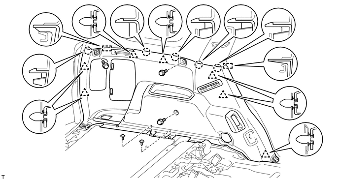
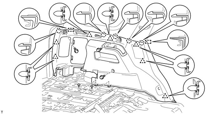
20. REMOVE DECK TRIM SIDE PANEL ASSEMBLY LH
(a) w/o Rear No. 2 Seat:
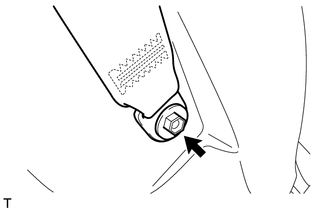
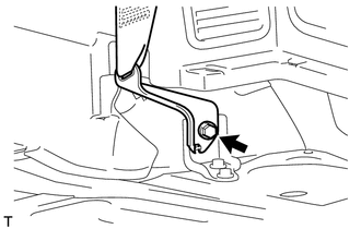
(1) Remove the bolt and disconnect the rear No. 1 seat outer belt floor anchor.
(2) Remove the 3 bolts and 2 screws.
(3) Detach the 7 clips, 5 claws and 2 guides and remove the deck trim side panel.
|
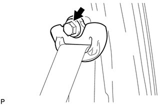
(4) Detach the 4 claws and 2 guides, pass the rear seatback lock control lever base through the deck trim side panel, and remove the deck trim side panel. |
|
(b) w/ Rear No. 2 Seat:
|
(1) Remove the bolt and disconnect the rear No. 1 seat outer belt floor anchor. |
|
|
(2) Remove the bolt and disconnect the rear No. 2 seat outer belt floor anchor. |
|
|
(3) for RH Side: Remove the bolt and disconnect the rear No. 2 seat outer belt floor anchor. |
|
(4) Remove the 3 bolts and 2 screws.
(5) Detach the 7 clips, 5 claws and 2 guides.
21. REMOVE REAR NO. 2 WINDOW SIDE GARNISH ASSEMBLY LH
22. REMOVE REAR WINDOW SIDE GARNISH ASSEMBLY LH
23. REMOVE REAR NO. 2 SEATBACK LOCK STRIKER SUB-ASSEMBLY LH (w/o Rear No. 2 Seat)
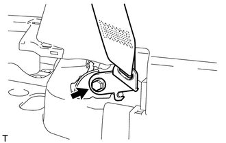
24. REMOVE REAR NO. 1 SEAT OUTER BELT ASSEMBLY LH
|
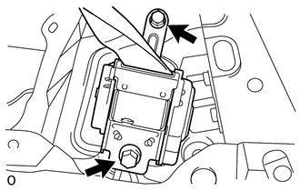
(a) Remove the bolt and rear No. 1 seat outer belt shoulder anchor. |
|
|
(b) Remove the 2 bolts and rear No. 1 seat outer belt assembly. |
|
 Inspection
INSPECTION
PROCEDURE
1. INSPECT REAR NO. 1 SEAT OUTER BELT ASSEMBLY
(a) Check the ELR.
(1) When the inclination of the retractor is 15° or less, check that
the belt can be pulled ...
 Installation
INSTALLATION
CAUTION / NOTICE / HINT
HINT:
Use the same procedure for the RH and LH sides.
The procedure listed below is for the LH side.
A bolt without a torque specification is sh ...
Other materials about Toyota 4Runner:
Removal
REMOVAL
PROCEDURE
1. DRAIN ENGINE COOLANT
(a) Drain engine coolant (See page ).
2. REMOVE RADIATOR ASSEMBLY
(a) Remove the radiator assembly (See page ).
3. RECOVER REFRIGERANT FROM REFRIGERATION SYSTEM
4. DISCONNECT DISCHARGE HOSE SUB-ASSEMBLY
...
Removal
REMOVAL
CAUTION / NOTICE / HINT
NOTICE:
When using a vise, do not overtighten it.
When installing the parts indicated by arrows, coat them with power
steering fluid (See page ).
PROCEDURE
1. DISCONNECT CABLE FROM NEGATIVE BATTERY TE ...

0.0131