Toyota 4Runner: Removal
REMOVAL
PROCEDURE
1. DISCONNECT CABLE FROM NEGATIVE BATTERY TERMINAL
CAUTION:
Wait at least 90 seconds after disconnecting the cable from the negative (-) battery terminal to disable the SRS system.
NOTICE:
When disconnecting the cable, some systems need to be initialized after the cable
is reconnected (See page .gif) ).
).
2. REMOVE DOOR SCUFF PLATE ASSEMBLY RH
HINT:
Use the same procedure as for the LH side (See page
).
3. REMOVE COWL SIDE TRIM BOARD RH
4. REMOVE NO. 2 INSTRUMENT CLUSTER FINISH PANEL GARNISH
5. REMOVE NO. 2 INSTRUMENT PANEL UNDER COVER SUB-ASSEMBLY
6. REMOVE FRONT NO. 2 CONSOLE BOX INSERT
7. REMOVE LOWER INSTRUMENT COVER LH
8. REMOVE LOWER NO. 2 INSTRUMENT PANEL AIRBAG ASSEMBLY
|
(a) Remove the 3 bolts. |
|
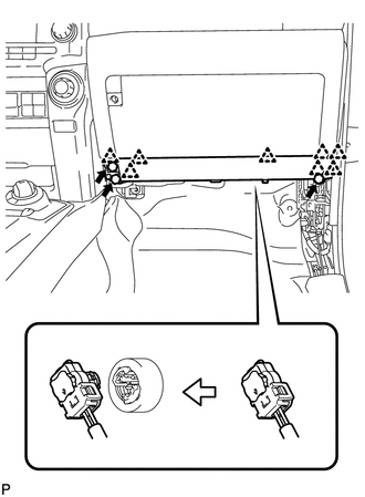
(b) Detach the 8 claws and remove the instrument panel airbag.
(c) Disconnect the connector.
NOTICE:
When handling the airbag connector, take care not to damage the airbag wire harness.
 On-vehicle Inspection
ON-VEHICLE INSPECTION
PROCEDURE
1. CHECK LOWER NO. 2 INSTRUMENT PANEL AIRBAG ASSEMBLY (VEHICLE NOT INVOLVED IN
COLLISION)
(a) Perform a diagnostic system check (See page
).
(b) With the lower ...
 Disposal
DISPOSAL
CAUTION / NOTICE / HINT
CAUTION:
Before performing pre-disposal deployment of any SRS part, review and closely
follow all applicable environmental and hazardous material regulations. Pre ...
Other materials about Toyota 4Runner:
Rear Shock Absorber(w/ Reas)
Components
COMPONENTS
ILLUSTRATION
Removal
REMOVAL
CAUTION / NOTICE / HINT
NOTICE:
Be sure to read the precaution before performing this procedure (See page
).
HINT:
Use the same procedure for the RH and LH sides.
The procedure lis ...
How To Proceed With Troubleshooting
CAUTION / NOTICE / HINT
HINT:
Use these procedures to troubleshoot the lighting system.
*: Use the Techstream.
PROCEDURE
1.
VEHICLE BROUGHT TO WORKSHOP
NEXT
...

0.0114