Toyota 4Runner: Removal
REMOVAL
CAUTION / NOTICE / HINT
HINT:
- Use the same procedure for the RH and LH sides.
- The procedure listed below is for the LH side.
PROCEDURE
1. REMOVE FRONT WHEEL
2. DRAIN DIFFERENTIAL OIL
.gif)
3. REMOVE FRONT AXLE HUB GREASE CAP
4. REMOVE FRONT AXLE SHAFT NUT
5. REMOVE FRONT SPEED SENSOR
6. DISCONNECT TIE ROD END SUB-ASSEMBLY LH
7. DISCONNECT FRONT LOWER BALL JOINT ATTACHMENT LH
.png)
(a) Remove the 2 bolts and disconnect the lower ball joint attachment from the steering knuckle.
8. REMOVE FRONT DRIVE SHAFT ASSEMBLY LH
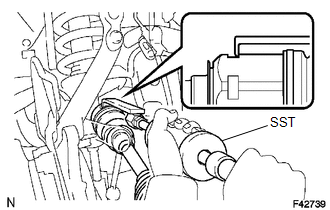
(a) Using SST, remove the front drive shaft.
SST: 09520-01010
SST: 09520-24010
09520-32040
NOTICE:
- Be careful not to damage the dust cover or oil seal.
- Keep the drive shaft level while handling it.
 Components
COMPONENTS
ILLUSTRATION
ILLUSTRATION
...
 Disassembly
DISASSEMBLY
PROCEDURE
1. REMOVE FRONT NO. 2 AXLE INBOARD JOINT BOOT CLAMP
(a) Hold the drive shaft lightly in a vise between aluminum plates.
(b) Using pliers, remove the front No. 2 ax ...
Other materials about Toyota 4Runner:
Precaution
PRECAUTION
1. IGNITION SWITCH EXPRESSION
HINT:
The type of ignition switch used on this model differs according to the specifications
of the vehicle. The expressions listed in the table below are used in this section.
Expression
Ign ...
Rear Wiper does not Operate
DESCRIPTION
The windshield wiper switch controls the rear wiper motor.
WIRING DIAGRAM
CAUTION / NOTICE / HINT
HINT:
Since the wiper and washer system has functions that use LIN communication, first
confirm that there is no malfunction in the communica ...

0.0066