Toyota 4Runner: Disassembly
DISASSEMBLY
PROCEDURE
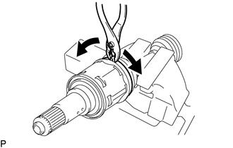
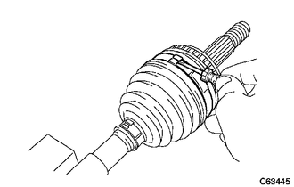
1. REMOVE FRONT NO. 2 AXLE INBOARD JOINT BOOT CLAMP
(a) Hold the drive shaft lightly in a vise between aluminum plates.
|
(b) Using pliers, remove the front No. 2 axle inboard joint boot clamp as shown in the illustration. |
|
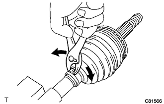
2. REMOVE FRONT NO. 1 AXLE INBOARD JOINT BOOT CLAMP
(a) Remove the front axle inboard joint boot clamp.
HINT:
Perform the same procedures as for the front No. 2 axle inboard joint boot clamp.
3. REMOVE FRONT AXLE INBOARD JOINT BOOT
4. REMOVE FRONT AXLE INBOARD JOINT SET
|
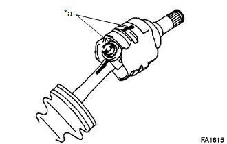
(a) Place matchmarks on the tripod and the inboard and outboard joint shafts. Text in Illustration
NOTICE: Do not punch the marks. |
|
(b) Remove the inboard joint from the outboard joint shaft.
|
(c) Using a snap ring expander, remove the snap ring. |
|
|
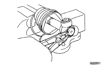
(d) Place matchmarks on the outboard joint shaft and tripod. Text in Illustration
NOTICE: Do not punch the marks. |
|
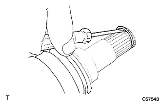
(e) Using a brass bar and hammer, remove the tripod from the drive shaft.
NOTICE:
Do not tap the roller.
5. REMOVE FRONT NO. 2 AXLE OUTBOARD JOINT BOOT CLAMP
|
(a) Using a screwdriver, remove the outboard joint boot clamps. HINT: If the outboard joint boot clamps that have been replaced are installed to the drive shaft, use a side cutter to remove them. |
|
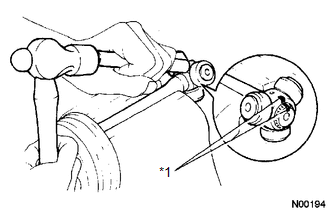
6. REMOVE FRONT NO. 1 AXLE OUTBOARD JOINT BOOT CLAMP
(a) Using pliers, remove the boot clamp, as shown in the illustration.
7. REMOVE OUTBOARD JOINT BOOT
8. REMOVE SHAFT SNAP RING
(a) Using a screwdriver, remove the snap ring.
9. REMOVE FRONT DRIVE SHAFT DUST COVER
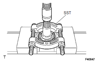
(a) Using SST and a press, remove the dust cover.
SST: 09950-00020
 Removal
REMOVAL
CAUTION / NOTICE / HINT
HINT:
Use the same procedure for the RH and LH sides.
The procedure listed below is for the LH side.
PROCEDURE
1. REMOVE FRONT WHEEL
2. DRAIN DI ...
 Inspection
INSPECTION
PROCEDURE
1. INSPECT FRONT DRIVE SHAFT ASSEMBLY
NOTICE:
Keep the drive shaft level while handling it.
(a) Check if there is excessive play in the outboard joint.
(b) Check if the in ...
Other materials about Toyota 4Runner:
Vehicle Lift And Support Locations
VEHICLE LIFT AND SUPPORT LOCATIONS
1. NOTICE ABOUT VEHICLE CONDITION WHEN RAISING VEHICLE
(a) The vehicle must be unloaded before jacking up or raising the vehicle. Never
jack up or raise a heavily loaded vehicle.
(b) When removing any heavy components li ...
Skid Control ECU Communication Stop Mode
DESCRIPTION
Detection Item
Symptom
Trouble Area
Brake Actuator (Skid Control ECU) Communication Stop Mode
Either condition is met:
"Skid Control (ABS/VSC/TRAC)" is not displa ...

0.0207