Toyota 4Runner: Removal
REMOVAL
PROCEDURE
1. REMOVE FRONT EXHAUST PIPE
(a) Remove the front exhaust pipe (See page .gif)
).
2. REMOVE FRONT PROPELLER SHAFT ASSEMBLY
|
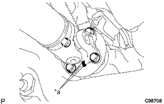
(a) Place matchmarks on the propeller shaft flange and differential. Text in Illustration
|
|
(b) Remove the 4 nuts and 4 bolts.
|
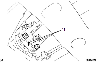
(c) Place matchmarks on the propeller shaft flange and transfer flange. Text in Illustration
|
|
(d) Remove the 4 nuts, 4 washers and front propeller shaft assembly.
 Components
COMPONENTS
ILLUSTRATION
...
 Disassembly
DISASSEMBLY
PROCEDURE
1. REMOVE FRONT UNIVERSAL JOINT SPIDER BEARING
HINT:
Use the same procedure for all front propeller shaft universal joint spider bearing.
(a) Place matchmarks on ...
Other materials about Toyota 4Runner:
Slide Sensor Malfunction (B2650)
DESCRIPTION
When the front power seat switch LH does not receive a sensor signal despite
forward or backward movement of the seat by power seat motor operation, this DTC
is stored.
DTC Code
DTC Detection Condition
Trouble ...
Alarm
The system sounds the alarm and flashes the lights when forced entry is
detected.
Triggering of the alarm
The alarm is triggered in the following situations when the alarm is set:
• A locked door is unlocked or opened in any way other than using the ...
0.0255


