Toyota 4Runner: Disassembly
DISASSEMBLY
PROCEDURE
1. REMOVE FRONT UNIVERSAL JOINT SPIDER BEARING
HINT:
Use the same procedure for all front propeller shaft universal joint spider bearing.
|
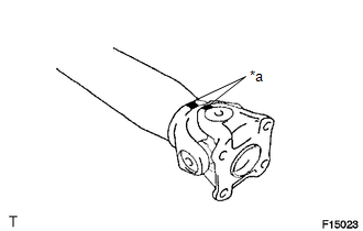
(a) Place matchmarks on the flange yoke and sleeve yoke. Text in Illustration
|
|
|
(b) Using a brass bar and hammer, slightly tap in the spider bearing outer races. |
|
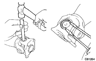
(c) Using 2 screwdrivers, remove the 4 snap rings from the grooves.
|
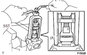
(d) Using SST, remove the spider bearing from the propeller shaft. SST: 09332-25010 HINT: Before installing SST, sufficiently raise the part labeled A. If the part labeled A is too low, it may be difficult to install SST. |
|
|
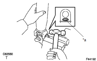
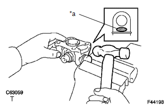
(e) Clamp the spider bearing outer race in a vise between aluminum plates and tap off the propeller shaft with a hammer. Text in Illustration
HINT: Remove the bearing on opposite side in the same procedure. NOTICE: Do not tap the shaft. |
|
|
(f) Install the 2 removed spider bearing outer races to the universal joint spider. |
|
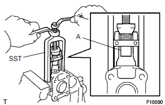
(g) Using SST, remove the bearing from the yoke.
SST: 09332-25010
HINT:
Before installing SST, sufficiently raise the part labeled A. If the part labeled A is too low, it may be difficult to install SST.
|
(h) Clamp the outer bearing race in a vise between aluminum plates and tap off the flange yoke with a hammer. Text in Illustration
|
|
(i) Remove the universal joint spider.
 Removal
REMOVAL
PROCEDURE
1. REMOVE FRONT EXHAUST PIPE
(a) Remove the front exhaust pipe (See page
).
2. REMOVE FRONT PROPELLER SHAFT ASSEMBLY
(a) Place matchmarks on the propeller shaft fl ...
 Inspection
INSPECTION
PROCEDURE
1. INSPECT FRONT PROPELLER SHAFT ASSEMBLY
(a) Using a dial indicator, check the propeller shaft runout.
Maximum runout:
0.3 mm (0.0118 in.)
If the shaft ru ...
Other materials about Toyota 4Runner:
How To Proceed With Troubleshooting
CAUTION / NOTICE / HINT
HINT:
*: Use the Techstream.
PROCEDURE
1.
VEHICLE BROUGHT TO WORKSHOP
NEXT
2.
CUSTOMER PROBLEM ANALYSIS
...
Stop Light Control Relay Malfunction (C1380)
DESCRIPTION
Upon receiving the hill-start assist control operating signal from the master
cylinder solenoid (skid control ECU), the Stop light control relay (Stop light switch
assembly) contact turns on and the stop lights come on.
DTC No.
...

0.007