Toyota 4Runner: Removal
REMOVAL
PROCEDURE
1. REMOVE PROPELLER SHAFT ASSEMBLY
|
(a) Place matchmarks on the propeller shaft flange and differential flange. Text in Illustration
|
|
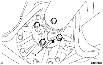
(b) Remove the 4 nuts, 4 bolts and 4 washers.
|
(c) Remove the propeller shaft. |
|
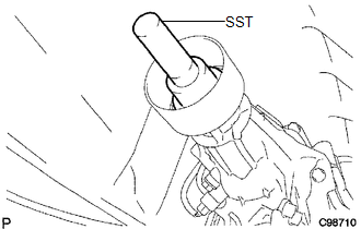
(d) Insert SST into the transmission to prevent oil leakage.
SST: 09325-40010
 Disassembly
DISASSEMBLY
PROCEDURE
1. REMOVE REAR PROPELLER SHAFT UNIVERSAL JOINT SPIDER BEARING
HINT:
Use the same procedure for all rear propeller shaft universal joint spider bearing.
(a) Place ...
 Inspection
INSPECTION
PROCEDURE
1. INSPECT PROPELLER SHAFT ASSEMBLY
(a) Using a dial indicator, check the propeller shaft runout.
Maximum runout:
0.4 mm (0.0157 in.)
If the shaft runout i ...
Other materials about Toyota 4Runner:
Brake Booster Pump Motor on Time Abnormally Long (C1252)
DESCRIPTION
The motor relay (semiconductor relay) is built into the master cylinder solenoid
and drives the pump motor based on a signal from the skid control ECU.
DTC Code
DTC Detection Condition
Trouble Area
...
On-vehicle Inspection
ON-VEHICLE INSPECTION
PROCEDURE
1. CHECK STEERING PAD (VEHICLE NOT INVOLVED IN COLLISION)
(a) Perform a diagnostic system check (See page
).
(b) With the steering pad installed on the vehicle, perform a visual check. If
there are any defects as mention ...

0.0272