Toyota 4Runner: Inspection
INSPECTION
PROCEDURE
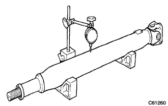
1. INSPECT PROPELLER SHAFT ASSEMBLY
|
(a) Using a dial indicator, check the propeller shaft runout. Maximum runout: 0.4 mm (0.0157 in.) If the shaft runout is more than the maximum, replace the shaft. |
|
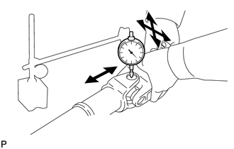
2. INSPECT REAR PROPELLER SHAFT UNIVERSAL JOINT SPIDER BEARING
NOTICE:
Be careful not to grip the propeller shaft tube too tightly in a vise as this will cause deformation.
(a) Check the spider bearings for wear or damage.
If necessary, replace the spider bearing.
|
(b) Check the spider bearing axial play by turning the yoke while holding the shaft tightly. Maximum bearing axial play: 0 mm (0 in.) If the axial play is more than the maximum, replace the spider bearing. |
|
 Removal
REMOVAL
PROCEDURE
1. REMOVE PROPELLER SHAFT ASSEMBLY
(a) Place matchmarks on the propeller shaft flange and differential flange.
Text in Illustration
*a
...
 Reassembly
REASSEMBLY
PROCEDURE
1. INSTALL REAR PROPELLER SHAFT UNIVERSAL JOINT SPIDER BEARING
HINT:
Use the same procedure for all rear propeller shaft universal joint spider bearing.
(a) Apply ...
Other materials about Toyota 4Runner:
Data List / Active Test
DATA LIST / ACTIVE TEST
1. DATA LIST
HINT:
Using the Techstream to read the Data List allows the values or states of switches,
sensors, actuators and other items to be read without removing any parts. This non-intrusive
inspection can be very useful bec ...
LVDS Signal Malfunction (from Extension Module) (B1532)
DESCRIPTION
DTC No.
DTC Detection Condition
Trouble Area
B1532
When one of the conditions below is met:
Stereo component tuner assembly is/was not connected while the
ignition sw ...

0.0273