Toyota 4Runner: Removal
REMOVAL
PROCEDURE
1. REMOVE PROPELLER SHAFT ASSEMBLY
|
(a) Place matchmarks on the propeller shaft flange and transfer flange. Text in Illustration
|
|
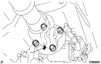
(b) Remove the 4 nuts, 4 washers and propeller shaft assembly.
|
(c) Place matchmarks on the propeller shaft flange and differential flange. Text in Illustration
|
|
.png)
(d) Remove the 4 nuts, 4 bolts and 4 washers.
 Components
COMPONENTS
ILLUSTRATION
...
 Disassembly
DISASSEMBLY
PROCEDURE
1. REMOVE REAR PROPELLER SHAFT UNIVERSAL JOINT SPIDER BEARING
HINT:
Use the same procedure for all rear propeller shaft universal joint spider bearing.
(a) Place ...
Other materials about Toyota 4Runner:
Inspection
INSPECTION
PROCEDURE
1. INSPECT FRONT POWER WINDOW REGULATOR MOTOR ASSEMBLY LH
(a) Check that the motor gear rotates smoothly as follows.
NOTICE:
Do not apply positive (+) battery voltage to any terminals except terminal
2 (B) to avoid ...
Removal
REMOVAL
PROCEDURE
1. REMOVE FRONT BUMPER COVER (w/o Intuitive Parking Assist System)
(See Page )
2. REMOVE FRONT BUMPER COVER (w/ Intuitive Parking Assist System)
(See Page )
3. REMOVE HIGH PITCHED HORN ASSEMBLY
4. REMOVE RADIATOR GRILLE BRACKET
...

0.0068