Toyota 4Runner: Replacement
REPLACEMENT
PROCEDURE
1. RECOVER REFRIGERANT FROM REFRIGERATION SYSTEM
(a) Start the engine.
(b) Turn the A/C switch on.
(c) Operate the cooler compressor while the engine speed is approximately 1000 rpm for 5 to 6 minutes to circulate the refrigerant and collect the compressor oil remaining in each component into the cooler compressor.
(d) Stop the engine.
(e) Recover the refrigerant from the A/C system using a refrigerant recovery unit.
2. CHARGE REFRIGERANT
SST: 09985-20010
09985-02130
09985-02150
09985-02090
09985-02110
09985-02010
09985-02050
09985-02060
09985-02070
(a) Perform vacuum purging using a vacuum pump.
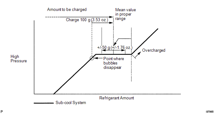
(b) Charge refrigerant HFC-134a (R134a).
Standard:
550 +/-30 g (19.3 +/-1.0 oz.)
NOTICE:
- Do not operate the cooler compressor before charging refrigerant as the cooler compressor does not work properly without any refrigerant and overheats.
- Approximately 100 g (3.53 oz.) of refrigerant may need to be charged after bubbles disappear.
3. WARM UP ENGINE
(a) Warm up the engine at less than 1850 rpm for 2 minutes or more after charging the refrigerant.
NOTICE:
Be sure to warm up the compressor by turning the A/C switch on after removing and installing the cooler refrigerant lines (including the compressor) to prevent damage to the compressor.
4. CHECK FOR REFRIGERANT GAS LEAK
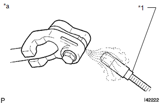
(a) After recharging the refrigerant gas, check for refrigerant gas leakage using a halogen leak detector.
(b) Perform the operation under these conditions:
- Stop the engine.
- Secure good ventilation (the halogen leak detector may react to volatile gases other than refrigerant, such as evaporated gasoline or exhaust gas).
- Repeat the test 2 or 3 times.
- Make sure that some refrigerant remains in the refrigeration system. When the compressor is off: approximately 392 to 588 kPa (4.0 to 6.0 kgf/cm2, 57 to 85 psi).
|
(c) Using a halogen leak detector, check the refrigerant line for leakage. Text in Illustration
|
|
(d) If a gas leak from the drain hose is not detected, remove the blower motor control (blower resistor) from the cooling unit. Insert the halogen leak detector sensor into the unit and perform the test.
(e) Disconnect the connector and wait for approximately 20 minutes. Bring the halogen leak detector close to the pressure switch and perform the test.
 On-vehicle Inspection
ON-VEHICLE INSPECTION
PROCEDURE
1. INSPECT REFRIGERANT PRESSURE WITH MANIFOLD GAUGE SET
(a) This method uses a manifold gauge set to locate problem areas. Read the manifold
gauge pressure when th ...
 Refrigerant Line
Components
COMPONENTS
ILLUSTRATION
...
Other materials about Toyota 4Runner:
Installation
INSTALLATION
PROCEDURE
1. INSTALL INSTRUMENT PANEL PASSENGER AIRBAG ASSEMBLY
(a) Attach the 5 hooks (A).
Text in Illustration
*a
Hook A
*b
Hook B
...
Removal
REMOVAL
CAUTION / NOTICE / HINT
CAUTION:
Wear protective gloves. Sharp areas on the parts may injure your hands.
HINT:
Use the same procedure for the RH and LH sides.
The procedure listed below is for the LH side.
PROCEDURE
1. REMOVE D ...

0.0086