Toyota 4Runner: Removal
REMOVAL
CAUTION / NOTICE / HINT
CAUTION:
Wear protective gloves. Sharp areas on the parts may injure your hands.
HINT:
- Use the same procedure for the RH and LH sides.
- The procedure listed below is for the LH side.
PROCEDURE
1. REMOVE DECK BOARD ASSEMBLY
(a) Pull the 2 rear seat lock release straps and fold down the 2 headrests.
(b) Operate the 2 rear seat lock release levers and fold down the 2 seatbacks.
|
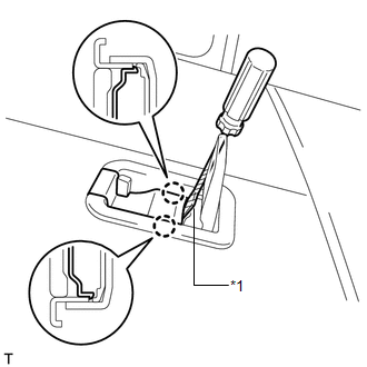
(c) Using a screwdriver, detach the 2 claws and open the cover. Text in Illustration
HINT:
|
|
|
(d) Remove the 2 bolts. |
|
(e) Detach the 4 clips and remove the deck board.
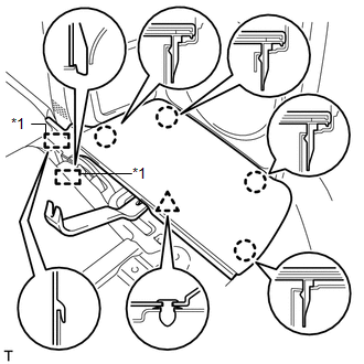
2. REMOVE REAR FLOOR MAT SUPPORT PLATE
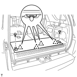
(a) Remove the 3 bolts.
 Text in Illustration
|
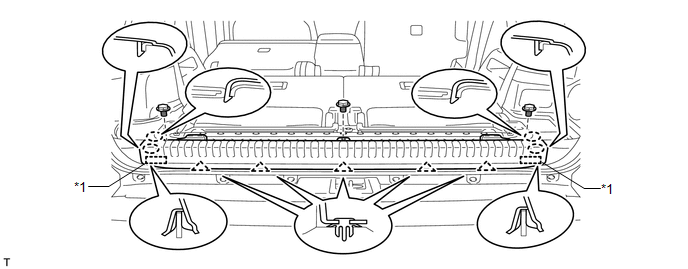
*1 |
Guide |
- |
- |
(b) Detach the 4 claws and 2 guides.
(c) Detach the 5 clips and remove the support plate.
3. REMOVE REAR NO. 4 FLOOR BOARD
|
(a) Using a moulding remover, detach the clip and 4 claws. Text in Illustration
|
|
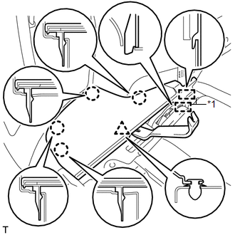
(b) Detach the 2 guides and remove the floor board.
4. REMOVE REAR NO. 3 FLOOR BOARD
|
(a) Using a moulding remover, detach the clip and 4 claws. Text in Illustration
|
|
(b) Detach the 2 guides and remove the floor board.
5. REMOVE DECK BOARD BRACKET REINFORCEMENT
|
(a) Remove the 2 bolts. Text in Illustration
|
|
(b) Detach the 2 hooks and remove the reinforcement.
6. REMOVE NO. 1 DECK BOARD BRACKET LH
|
(a) Remove the 2 bolts and bracket. |
|
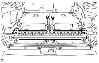
7. REMOVE REAR NO. 2 SEAT ASSEMBLY LH
(a) Operate the seat cushion lock release lever and raise the seatback.
(b) Pull out the seat cushion.
|
(c) Remove the 2 bolts. |
|
|
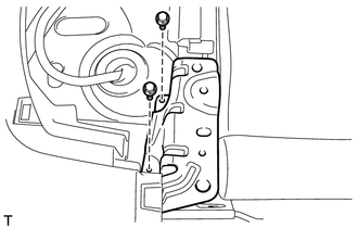
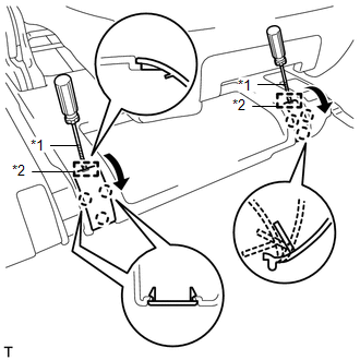
(d) Using a screwdriver, detach the 2 guides and 6 claws and open the 2 covers. Text in Illustration
HINT: Tape the screwdriver tip before use. |
|
|
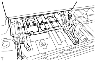
(e) Remove the 2 bolts. |
|
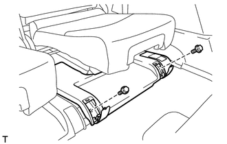
|
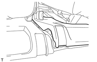
(f) Remove the rear No. 2 seat assembly from the vehicle. NOTICE: Be careful not to damage the vehicle body. HINT: If removing the seat on the RH side with the LH side installed, remove it with the No. 3 rear seat leg cover LH raised as shown in the illustration. |
|
 Reassembly
REASSEMBLY
CAUTION / NOTICE / HINT
CAUTION:
Wear protective gloves. Sharp areas on the parts may injure your hands.
HINT:
Use the same procedure for the RH and LH sides.
The procedure ...
 Installation
INSTALLATION
CAUTION / NOTICE / HINT
CAUTION:
Wear protective gloves. Sharp areas on the parts may injure your hands.
HINT:
Use the same procedure for the RH and LH sides.
The procedu ...
Other materials about Toyota 4Runner:
Engine Immobiliser System Malfunction (B2799)
DESCRIPTION
This DTC is stored when one of the following occurs: 1) the ECM detects errors
in its own communications with the transponder key ECU assembly; 2) the ECM detects
errors in the communication lines; or 3) the ECU - ECM communication ID between ...
Parts Location
PARTS LOCATION
ILLUSTRATION
ILLUSTRATION
ILLUSTRATION
ILLUSTRATION
ILLUSTRATION
...

0.0271