Toyota 4Runner: Runnable Signal Malfunction (B2286,P0335)
DESCRIPTION
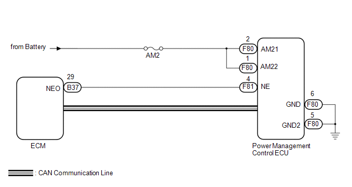
The power management control ECU and ECM are connected by a cable and the CAN communication lines. These DTCs are stored when the crankshaft position sensor signal information from the cable and the crankshaft position sensor signal information from the CAN communication line are inconsistent.
HINT:
When the power management control ECU is replaced with a new one and the cable is connected to the negative (-) battery terminal, the power source mode is reset to on (IG). When the battery is removed and reinstalled, the power source mode that was selected when the battery was removed is restored.
|
DTC Code |
DTC Detection Condition |
Trouble Area |
|---|---|---|
|
B2286 P0335 |
The crankshaft position sensor signal information from the cable and the crankshaft position sensor signal information from the CAN communication line are inconsistent. |
|
WIRING DIAGRAM
CAUTION / NOTICE / HINT
NOTICE:
- When using the Techstream with the engine switch off to troubleshoot: Connect the Techstream to the vehicle and turn a courtesy light switch on and off at 1.5 second intervals until communication between the Techstream and vehicle begins.
- Before performing the inspection, check that there are no problems related to the CAN communication system and LIN communication system.
- Inspect the fuses for circuits related to this system before performing the following inspection procedure.
PROCEDURE
|
1. |
CHECK HARNESS AND CONNECTOR (BATTERY - POWER MANAGEMENT CONTROL ECU) |
.gif)
| NG | .gif) |
REPAIR OR REPLACE HARNESS OR CONNECTOR |
|
.gif)
|
2. |
CHECK HARNESS AND CONNECTOR (POWER MANAGEMENT CONTROL ECU - BODY GROUND) |
| NG | |
REPAIR OR REPLACE HARNESS OR CONNECTOR |
|
|
3. |
CHECK HARNESS AND CONNECTOR (POWER MANAGEMENT CONTROL ECU - ECM) |
(a) Disconnect the F81 power management control ECU connector.
(b) Disconnect the B37 ECM connector.
(c) Measure the resistance according to the value(s) in the table below.
Standard Resistance:
|
Tester Connection |
Condition |
Specified Condition |
|---|---|---|
|
F81-4 (NE) - B37-29 (NEO) |
Always |
Below 1 Ω |
|
F81-4 (NE) - Body ground |
Always |
10 kΩ or higher |
| NG | |
REPAIR OR REPLACE HARNESS OR CONNECTOR |
|
|
4. |
READ VALUE USING TECHSTREAM (ENGINE CONDITION) |
(a) Connect the Techstream to the DLC3.
(b) Turn the engine switch on (IG).
(c) Turn the Techstream on.
(d) Enter the following menus: Body Electrical / Power Source Control / Data List.
(e) According to the display on the Techstream, read the Data List.
Power Source Control|
Tester Display |
Measurement Item/Range |
Normal Condition |
Diagnostic Note |
|---|---|---|---|
|
Engine Condition |
Engine condition / Stop or Run |
Stop: Engine stopped Run: Engine running |
- |
OK:
ON (engine stopped) or OFF (engine running) appears on the screen according to the engine condition.
| OK | |
GO TO SFI SYSTEM (HOW TO PROCEED WITH TROUBLE SHOOTING) |
|
|
5. |
CHECK POWER MANAGEMENT CONTROL ECU |
(a) Reconnect the power management control ECU connectors.
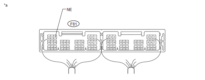 Text in Illustration
|
*a |
Component with harness connected (Power Management Control ECU) |
- |
- |
(b) Using an oscilloscope, check the engine speed input signal waveform at the terminal of the power management control ECU.
Standard Frequency:
|
Tester Connection |
Condition |
Specified Condition |
|---|---|---|
|
F81-4 (NE) - Body ground |
Engine stopped |
No pulse generated |
|
Engine running |
Pulse generated (1000 rpm: 200 Hz) |
| OK | |
REPLACE POWER MANAGEMENT CONTROL ECU |
| NG | |
GO TO SFI SYSTEM (HOW TO PROCEED WITH TROUBLE SHOOTING) |
 Steering Lock Position Signal Circuit Malfunction (B2285)
DESCRIPTION
The power management control ECU and steering lock actuator (steering lock ECU)
are connected by a cable and the LIN communication line. This DTC is stored when
the steering lock posi ...
 ACC Monitor Malfunction (B2274)
DESCRIPTION
This DTC is stored when there is a problem in the ACC output circuit, which is
from the ACC output terminal of the power management control ECU to the ACC relay.
HINT:
When the power ...
Other materials about Toyota 4Runner:
Installation
INSTALLATION
PROCEDURE
1. INSTALL VANE PUMP ASSEMBLY
(a) Install the vane pump with the 2 bolts.
Torque:
43 N·m {438 kgf·cm, 32 ft·lbf}
(b) Install the wire harness bracket with the bolt.
Torque:
43 N·m {438 kgf·cm, 32 ft·lbf}
2. CONNECT NO. 1 ...
Disassembly
DISASSEMBLY
PROCEDURE
1. REMOVE TRANSMISSION CONTROL SHAFT LEVER LH
(a) Remove the nut, spring washer and control shaft lever LH.
2. REMOVE PARK/NEUTRAL POSITION SWITCH ASSEMBLY
(a) Using a screwdriver, bend the tabs of the lock washer.
(b) Remove th ...

0.0231