Toyota 4Runner: Security Indicator Light Circuit
DESCRIPTION
- When the theft deterrent system is in the disarmed state, the security
indicator light flashes continuously when the engine immobiliser system
is set, and does not illuminate when the engine immobiliser system is not
set.
When the theft deterrent system is in the armed state, the engine immobiliser system is automatically set and the security indicator light flashes continuously.
When the theft deterrent system is in the arming preparation state or alarm sounding state, the main body ECU (multiplex network body ECU) causes the security indicator light to be illuminated.
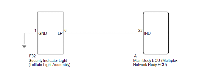
WIRING DIAGRAM
PROCEDURE
|
1. |
PERFORM ACTIVE TEST USING TECHSTREAM (SECURITY INDICATOR) |
(a) Operate the Techstream according to the steps on the display and select Active
Test (See page .gif) ).
).
Main Body
|
Tester Display |
Test Part |
Control Range |
Diagnostic Note |
|---|---|---|---|
|
Security Indicator |
Security indicator light |
ON/OFF |
The test is possible when the following conditions are met:
|
- *1: w/ Smart Key System
- *2: w/o Smart Key System
OK:
Security indicator light can be turned on and off using the Techstream.
| OK | .gif) |
PROCEED TO NEXT SUSPECTED AREA SHOWN IN PROBLEM SYMPTOMS TABLE |
|
.gif)
|
2. |
INSPECT SECURITY INDICATOR LIGHT (TELLTALE LIGHT ASSEMBLY) |
(a) Remove the security indicator light (telltale light assembly) (See page
).
(b) Inspect the security indicator light (telltale light assembly) (See page
).
| NG | |
REPLACE SECURITY INDICATOR LIGHT (TELLTALE LIGHT ASSEMBLY) |
|
|
3. |
CHECK HARNESS AND CONNECTOR (TELLTALE LIGHT - MAIN BODY ECU AND BODY GROUND) |
(a) Disconnect the F32 security indicator light (telltale light assembly) connector.
(b) Remove the main body ECU (multiplex network body ECU) from the driver side
junction block assembly (See page ).
(c) Measure the resistance according to the value(s) in the table below.
Standard Resistance:
|
Tester Connection |
Condition |
Specified Condition |
|---|---|---|
|
F32-6 (LP) - A-23 (IND) |
Always |
Below 1 Ω |
|
F32-1 (GND) - Body ground |
Always |
Below 1 Ω |
|
F32-6 (LP) or A-23 (IND) - Body ground |
Always |
10 kΩ or higher |
| OK | |
REPLACE MAIN BODY ECU (MULTIPLEX NETWORK BODY ECU) |
| NG | |
REPAIR OR REPLACE HARNESS OR CONNECTOR |
 Security Horn Circuit
DESCRIPTION
When the theft deterrent system is in the alarm sounding state, the main body
ECU outputs a signal repeatedly at 0.4 second intervals, causing the security horn
assembly to sound
WIR ...
 Transponder Key Amplifier
Components
COMPONENTS
ILLUSTRATION
Inspection
INSPECTION
PROCEDURE
1. INSPECT TRANSPONDER KEY AMPLIFIER
(a) Apply battery voltage to the connector and check the LED illuminatio ...
Other materials about Toyota 4Runner:
Security Indicator Light Circuit
DESCRIPTION
When the theft deterrent system is in the disarmed state, the security
indicator light flashes continuously when the engine immobiliser system
is set, and does not illuminate when the engine immobiliser system is not
set.
Whe ...
Key Reminder Buzzer does not Sound
DESCRIPTION
The key reminder warning buzzer sounds when the driver side door is opened while
the ignition switch is ACC or off and the key is in the ignition key cylinder. The
key reminder warning buzzer is activated when the main body ECU (multiplex netw ...

0.0066