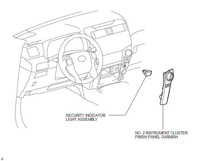
Toyota 4Runner: Security Indicator Light Assembly
Components
COMPONENTS
ILLUSTRATION
Removal
REMOVAL
PROCEDURE
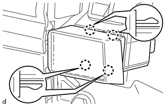
1. REMOVE NO. 2 INSTRUMENT CLUSTER FINISH PANEL GARNISH
.gif)
2. REMOVE SECURITY INDICATOR LIGHT ASSEMBLY
|
(a) Pull the security indicator light assembly to detach the 4 claws on the backside of the security indicator light assembly. |
|
(b) Disconnect the connector to remove the security indicator light assembly.
Inspection
INSPECTION
PROCEDURE
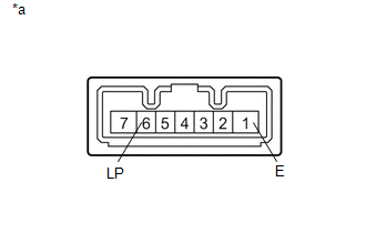
1. INSPECT SECURITY INDICATOR LIGHT ASSEMBLY
|
(a) Apply battery voltage between the terminals of the security indicator light assembly, and check that the security indicator light illuminates. OK:
If the result is not as specified, replace the security indicator light assembly. |
|
 Security Horn Assembly
Components
COMPONENTS
ILLUSTRATION
Removal
REMOVAL
PROCEDURE
1. REMOVE AIR CLEANER CAP AND HOSE
2. REMOVE AIR CLEANER CASE SUB-ASSEMBLY
3. REMOVE SECURITY HORN ASSEMBLY
...

Other materials about Toyota 4Runner:
Stop Light Control Relay Malfunction (C1380)
DESCRIPTION
Upon receiving the hill-start assist control operating signal from the master
cylinder solenoid (skid control ECU), the Stop light control relay (Stop light switch
assembly) contact turns on and the stop lights come on.
DTC No.
...
Removal
REMOVAL
PROCEDURE
1. REMOVE NO. 1 INSTRUMENT CLUSTER FINISH PANEL GARNISH
2. REMOVE NO. 2 INSTRUMENT CLUSTER FINISH PANEL GARNISH
3. REMOVE HEATER CONTROL ASSEMBLY
4. REMOVE SHIFT LEVER KNOB SUB-ASSEMBLY
5. REMOVE SHIFT LEVER KNOB SUB-ASSEMBL ...

0.0088