Toyota 4Runner: Security Horn Assembly
Components
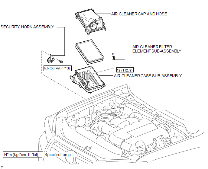
COMPONENTS
ILLUSTRATION
Removal
REMOVAL
PROCEDURE
1. REMOVE AIR CLEANER CAP AND HOSE
.gif)
2. REMOVE AIR CLEANER CASE SUB-ASSEMBLY
3. REMOVE SECURITY HORN ASSEMBLY
|
(a) Disconnect the connector. |
|
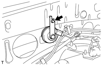
(b) Remove the bolt and horn.
Inspection
INSPECTION
PROCEDURE
1. INSPECT SECURITY HORN ASSEMBLY
(a) Apply battery voltage to the horn connector and check the operation of the horn.
OK:
|
Measurement Condition |
Specified Condition |
|---|---|
|
Battery positive (+) → Terminal 1 Battery negative (-) → Horn bracket |
Horn sounds |
If the result is not as specified, replace the security horn assembly.
Installation
INSTALLATION
PROCEDURE
1. INSTALL SECURITY HORN ASSEMBLY
(a) Install the horn with the bolt.
Torque:
5.5 N·m {56 kgf·cm, 49 in·lbf}
(b) Connect the connector.
2. INSTALL AIR CLEANER CASE SUB-ASSEMBLY
.gif)
3. INSTALL AIR CLEANER CAP AND HOSE
 Id Code Box
Components
COMPONENTS
ILLUSTRATION
Installation
INSTALLATION
PROCEDURE
1. INSTALL ID CODE BOX
(a) Attach the 2 claws and move the ID code box in the direction of the
arrow. ...
 Security Indicator Light Assembly
Components
COMPONENTS
ILLUSTRATION
Removal
REMOVAL
PROCEDURE
1. REMOVE NO. 2 INSTRUMENT CLUSTER FINISH PANEL GARNISH
2. REMOVE SECURITY INDICATOR LIGHT ASSEMBLY
(a) Pull th ...
Other materials about Toyota 4Runner:
Customize Parameters
CUSTOMIZE PARAMETERS
1. CUSTOMIZING FUNCTION WITH THE TECHSTREAM
HINT:
The following items can be customized.
NOTICE:
When the customer requests a change in a function, first make sure that
the function can be customized.
Record the curren ...
Downhill Assist Control Switch
Components
COMPONENTS
ILLUSTRATION
Removal
REMOVAL
PROCEDURE
1. REMOVE DRIVE MONITOR SWITCH
2. REMOVE MAP LIGHT ASSEMBLY
3. REMOVE DOWNHILL ASSIST CONTROL SWITCH
(a) Disconnect the 2 connectors.
...

0.017