Toyota 4Runner: Side Step
Components
COMPONENTS
ILLUSTRATION
ILLUSTRATION
Disassembly
DISASSEMBLY
CAUTION / NOTICE / HINT
HINT:
- Use the same procedure for the RH and LH sides.
- The procedure listed below is for the LH side.
PROCEDURE
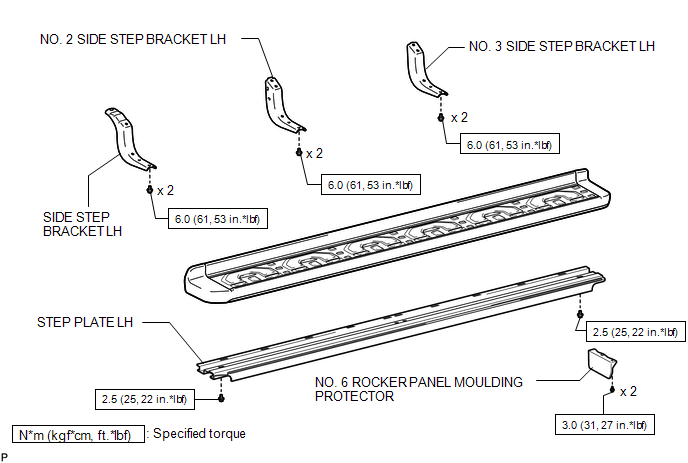
1. REMOVE SIDE STEP BRACKET LH
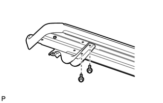
(a) Remove the 2 bolts and side step bracket.
2. REMOVE NO. 2 SIDE STEP BRACKET LH
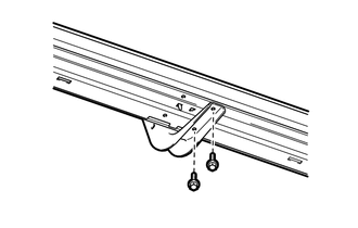
(a) Remove the 2 bolts and No. 2 side step bracket.
3. REMOVE NO. 3 SIDE STEP BRACKET LH
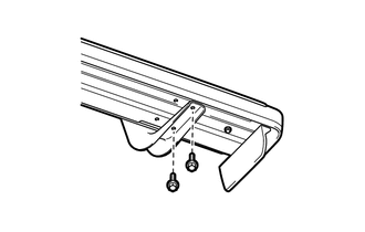
(a) Remove the 2 bolts and No. 3 side step bracket.
4. REMOVE NO. 6 ROCKER PANEL MOULDING PROTECTOR
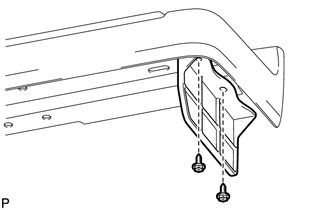
(a) Remove the 2 screws and No. 6 rocker panel moulding protector.
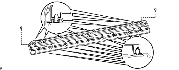
5. REMOVE STEP PLATE LH
(a) Remove the 2 bolts.
(b) Detach the 9 claws and 8 clips and remove the step plate.
Removal
REMOVAL
CAUTION / NOTICE / HINT
HINT:
- Use the same procedure for the RH and LH sides.
- The procedure listed below is for the LH side.
PROCEDURE
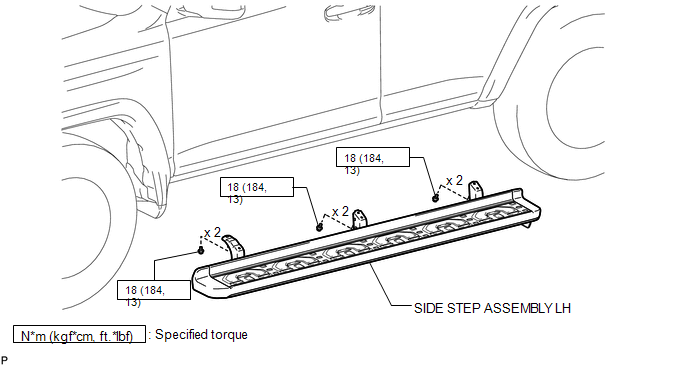
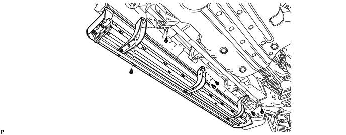
1. REMOVE SIDE STEP ASSEMBLY LH
(a) Remove the 6 bolts and side step.
Reassembly
REASSEMBLY
CAUTION / NOTICE / HINT
HINT:
- Use the same procedure for the RH and LH sides.
- The procedure listed below is for the LH side.
PROCEDURE
1. INSTALL STEP PLATE LH
(a) Attach the 9 claws and 8 clips to install the step plate.
(b) Install the 2 bolts.
Torque:
2.5 N·m {25 kgf·cm, 22 in·lbf}
2. INSTALL NO. 6 ROCKER PANEL MOULDING PROTECTOR
(a) Install the No. 6 rocker panel moulding protector with the 2 screws.
Torque:
3.0 N·m {31 kgf·cm, 27 in·lbf}
3. INSTALL SIDE STEP BRACKET LH
(a) Install the side step bracket with the 2 bolts.
Torque:
6.0 N·m {61 kgf·cm, 53 in·lbf}
4. INSTALL NO. 2 SIDE STEP BRACKET LH
(a) Install the No. 2 side step bracket with the 2 bolts.
Torque:
6.0 N·m {61 kgf·cm, 53 in·lbf}
5. INSTALL NO. 3 SIDE STEP BRACKET LH
(a) Install the No. 3 side step bracket with the 2 bolts.
Torque:
6.0 N·m {61 kgf·cm, 53 in·lbf}
Installation
INSTALLATION
CAUTION / NOTICE / HINT
HINT:
- Use the same procedure for the RH and LH sides.
- The procedure listed below is for the LH side.
PROCEDURE
1. INSTALL SIDE STEP ASSEMBLY LH
(a) Install the side step with the 6 bolts.
Torque:
18 N·m {184 kgf·cm, 13 ft·lbf}
 Installation
INSTALLATION
CAUTION / NOTICE / HINT
HINT:
Use the same procedure for both the RH and LH sides.
The procedure listed below is for the LH side.
PROCEDURE
1. INSTALL FRONT FENDER ...
 Horn
Horn
...
Other materials about Toyota 4Runner:
Combination Meter
Components
COMPONENTS
ILLUSTRATION
ILLUSTRATION
ILLUSTRATION
Removal
REMOVAL
PROCEDURE
1. DISCONNECT CABLE FROM NEGATIVE BATTERY TERMINAL
CAUTION:
Wait at least 90 seconds after disconnecting the cable from the negative (-)
battery termin ...
Data Signal Circuit between Navigation Receiver Assembly and Stereo Jack Adapter
DESCRIPTION
The No. 1 stereo jack adapter assembly sends the sound data signal or image data
signal from a USB device to the navigation receiver assembly via this circuit.
WIRING DIAGRAM
PROCEDURE
1.
CHECK HARNESS AND CONNECTOR ( ...

0.0279