Toyota 4Runner: Sound Signal Circuit between Navigation Receiver Assembly and Stereo Component Amplifier
DESCRIPTION
The navigation receiver assembly sends a sound signal to the stereo component amplifier assembly via the sound signal circuit.
The sound signal that has been sent is amplified by the stereo component amplifier assembly, and then is sent to the speakers.
If there is an open or short in the circuit, sound cannot be heard from the speakers even if there is no malfunction in the stereo component amplifier assembly, DCM (telematics transceiver)*1 or speakers.
- *1: w/ Manual (SOS) Switch
WIRING DIAGRAM
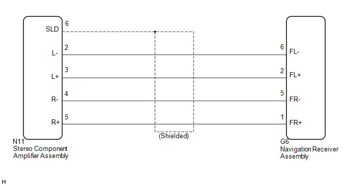
PROCEDURE
|
1. |
CHECK HARNESS AND CONNECTOR (NAVIGATION RECEIVER ASSEMBLY - STEREO COMPONENT AMPLIFIER ASSEMBLY) |
(a) Disconnect the G6 navigation receiver assembly connector.
(b) Disconnect the N11 stereo component amplifier assembly connector.
(c) Measure the resistance according to the value(s) in the table below.
Standard Resistance:
|
Tester Connection |
Condition |
Specified Condition |
|---|---|---|
|
N11-5 (R+) - G6-1 (FR+) |
Always |
Below 1 Ω |
|
N11-4 (R-) - G6-5 (FR-) |
Always |
Below 1 Ω |
|
N11-3 (L+) - G6-2 (FL+) |
Always |
Below 1 Ω |
|
N11-2 (L-) - G6-6 (FL-) |
Always |
Below 1 Ω |
|
N11-6 (SLD) - Body ground |
Always |
10 kΩ or higher |
|
N11-5 (R+) - Body ground |
Always |
10 kΩ or higher |
|
N11-4 (R-) - Body ground |
Always |
10 kΩ or higher |
|
N11-3 (L+) - Body ground |
Always |
10 kΩ or higher |
|
N11-2 (L-) - Body ground |
Always |
10 kΩ or higher |
| OK | .gif) |
PROCEED TO NEXT SUSPECTED AREA SHOWN IN PROBLEM SYMPTOMS TABLE |
| NG | |
REPAIR OR REPLACE HARNESS OR CONNECTOR |
 Speaker Circuit
DESCRIPTION
If there is a short in a speaker circuit, the stereo component amplifier
assembly detects it and stops output to the speakers.
Thus sound cannot be heard from the speakers ...
 Data Signal Circuit between Navigation Receiver Assembly and Extension Module
DESCRIPTION
The stereo component tuner assembly sends the sound data signal or image data
signal from a device to the navigation receiver assembly via this circuit.
WIRING DIAGRAM
CAUTION / NOT ...
Other materials about Toyota 4Runner:
Radio Receiver Power Source Circuit
DESCRIPTION
This is the power source circuit to operate the radio and display receiver assembly.
WIRING DIAGRAM
CAUTION / NOTICE / HINT
NOTICE:
Inspect the fuses for circuits related to this system before performing the following
inspection procedure. ...
Removal
REMOVAL
PROCEDURE
1. DISCONNECT CABLE FROM NEGATIVE BATTERY TERMINAL
CAUTION:
Wait at least 90 seconds after disconnecting the cable from the negative (-)
battery terminal to disable the SRS system.
NOTICE:
When disconnecting the cable, some systems ne ...

0.0089