Toyota 4Runner: Sound Signal Circuit between Navigation Receiver Assembly and Stereo Jack Adapter
DESCRIPTION
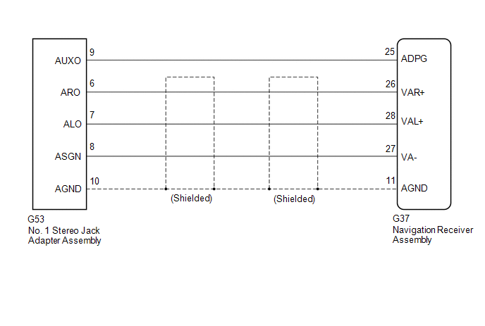
The No. 1 stereo jack adapter assembly sends the sound signal from an external device to the navigation receiver assembly via this circuit.
The sound signal that has been sent is amplified by the stereo component amplifier assembly, and then is sent to the speakers.
If there is an open or short in the circuit, sound cannot be heard from the speakers even if there is no malfunction in the stereo component amplifier assembly, DCM (telematics transceiver)*1 or speakers.
- *1: w/ Manual (SOS) Switch
WIRING DIAGRAM
PROCEDURE
|
1. |
CHECK HARNESS AND CONNECTOR (NAVIGATION RECEIVER ASSEMBLY - NO. 1 STEREO JACK ADAPTER ASSEMBLY) |
|
(a) Disconnect the G37 navigation receiver assembly connector. |
|
(b) Disconnect the G53 No. 1 stereo jack adapter assembly connector.
(c) Measure the resistance according to the value(s) in the table below.
Standard Resistance:
|
Tester Connection |
Condition |
Specified Condition |
|---|---|---|
|
G37-25 (ADPG) - G53-9 (AUXO) |
Always |
Below 1 Ω |
|
G37-26 (VAR+) - G53-6 (ARO) |
Always |
Below 1 Ω |
|
G37-28 (VAL+) - G53-7 (ALO) |
Always |
Below 1 Ω |
|
G37-27 (VA-) - G53-8 (ASGN) |
Always |
Below 1 Ω |
|
G37-11 (AGND) - G53-10 (AGND) |
Always |
Below 1 Ω |
|
G37-25 (ADPG) - Body ground |
Always |
10 kΩ or higher |
|
G37-26 (VAR+) - Body ground |
Always |
10 kΩ or higher |
|
G37-28 (VAL+) - Body ground |
Always |
10 kΩ or higher |
|
G37-27 (VA-) - Body ground |
Always |
10 kΩ or higher |
|
G37-11 (AGND) - Body ground |
Always |
10 kΩ or higher |
|
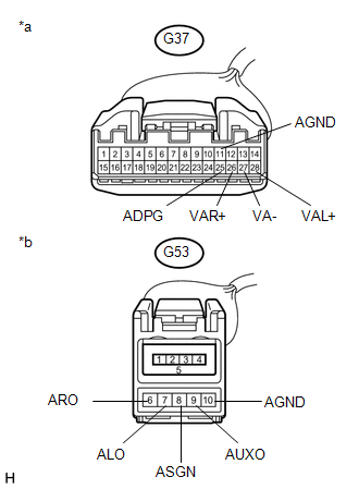
*a |
Front view of wire harness connector (to Navigation Receiver Assembly) |
|
*b |
Front view of wire harness connector (to No. 1 Stereo Jack Adapter Assembly) |
| OK | .gif) |
PROCEED TO NEXT SUSPECTED AREA SHOWN IN PROBLEM SYMPTOMS TABLE |
| NG | |
REPAIR OR REPLACE HARNESS OR CONNECTOR |
 Data Signal Circuit between Navigation Receiver Assembly and Extension Module
DESCRIPTION
The stereo component tuner assembly sends the sound data signal or image data
signal from a device to the navigation receiver assembly via this circuit.
WIRING DIAGRAM
CAUTION / NOT ...
 Data Signal Circuit between Navigation Receiver Assembly and Stereo Jack Adapter
DESCRIPTION
The No. 1 stereo jack adapter assembly sends the sound data signal or image data
signal from a USB device to the navigation receiver assembly via this circuit.
WIRING DIAGRAM
PROCED ...
Other materials about Toyota 4Runner:
Unable to Unlock Steering Wheel (Engine cannot Start)
DESCRIPTION
The power management control ECU supplies the power to activate the motor of
the steering lock actuator assembly.
The steering lock actuator activates the steering lock motor and moves the lock
bar into the steering column to lock the steerin ...
Menu list of the hands-free phone system
Normal operation
Using a short cut key
Automatic volume adjustment
When vehicle speed reaches 50 mph (80 km/h) or more, the volume automatically
increases. The volume returns to the previous volume setting when vehicle speed
drops to 43 mph (70 k ...

0.0122