Toyota 4Runner: Speaker Output Short (B15C3)
DESCRIPTION
This DTC is stored when a malfunction occurs in the speakers.
|
DTC No. |
DTC Detection Condition |
Trouble Area |
|---|---|---|
|
B15C3 |
A short is detected in the speaker output circuit. |
|
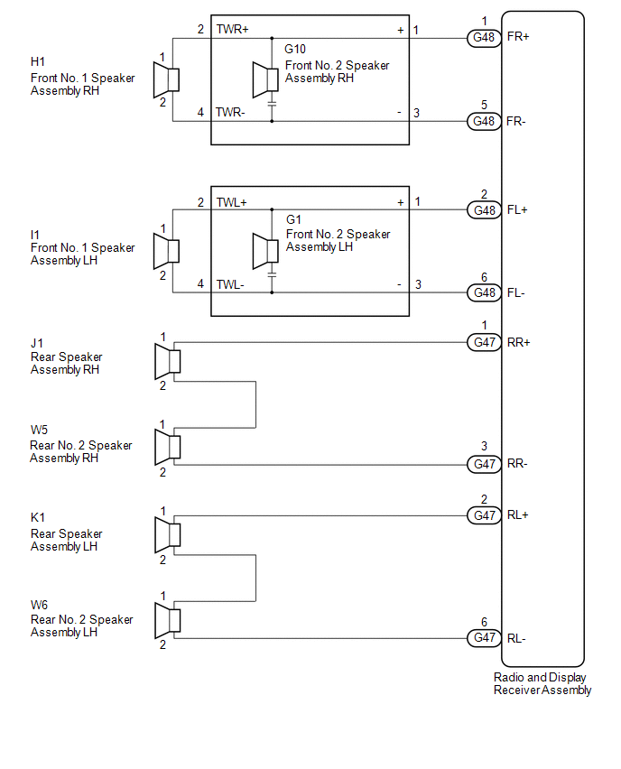
WIRING DIAGRAM
PROCEDURE
|
1. |
CHECK HARNESS AND CONNECTOR |
(a) Disconnect the G47 and G48 radio and display receiver assembly connectors.
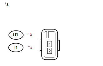
(b) Disconnect the H1 and I1 front No. 1 speaker assembly connectors.
(c) Disconnect the G1 and G10 front No. 2 speaker assembly connectors.
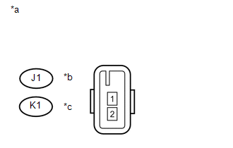
(d) Disconnect the J1 and K1 rear speaker assembly connectors.
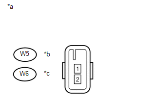
(e) Disconnect the W5 and W6 rear No. 2 speaker assembly connectors.
(f) Measure the resistance between the radio and display receiver assembly and body ground to check for a short circuit in the wire harness.
Standard Resistance:
|
Tester Connection |
Condition |
Specified Condition |
|---|---|---|
|
G47-1 (RR+) - Body ground |
Always |
10 kΩ or higher |
|
G47-2 (RL+) - Body ground |
Always |
10 kΩ or higher |
|
G47-3 (RR-) - Body ground |
Always |
10 kΩ or higher |
|
G47-6 (RL-) - Body ground |
Always |
10 kΩ or higher |
|
G48-1 (FR+) - Body ground |
Always |
10 kΩ or higher |
|
G48-2 (FL+) - Body ground |
Always |
10 kΩ or higher |
|
G48-5 (FR-) - Body ground |
Always |
10 kΩ or higher |
|
G48-6 (FL-) - Body ground |
Always |
10 kΩ or higher |
(g) Measure the resistance between each of the front No. 2 speaker assemblies and body ground to check for a short circuit in the wire harness.
Standard Resistance:
|
Tester Connection |
Condition |
Specified Condition |
|---|---|---|
|
G1-2 (TWL+) - Body ground |
Always |
10 kΩ or higher |
|
G1-4 (TWL-) - Body ground |
Always |
10 kΩ or higher |
|
G10-2 (TWR+) - Body ground |
Always |
10 kΩ or higher |
|
G10-4 (TWR-) - Body ground |
Always |
10 kΩ or higher |
(h) Measure the resistance between each of the rear speaker assemblies and rear No. 2 speaker assemblies to check for a short circuit in the wire harness.
Standard Resistance:
|
Tester Connection |
Condition |
Specified Condition |
|---|---|---|
|
J1-2 - Body ground |
Always |
10 kΩ or higher |
|
K1-2 - Body ground |
Always |
10 kΩ or higher |
| NG | .gif) |
REPAIR OR REPLACE HARNESS OR CONNECTOR |
|
.gif)
|
2. |
INSPECT FRONT NO. 1 SPEAKER ASSEMBLY |
|
(a) Measure the resistance according to the value(s) in the table below. Standard Resistance:
|
|
| NG | |
REPLACE FRONT NO. 1 SPEAKER ASSEMBLY |
|
|
3. |
REPLACE FRONT NO. 2 SPEAKER ASSEMBLY |
(a) Replace the front No. 2 speaker assembly with a known good one (See page
.gif) ).
).
(b) Clear the DTCs (See page ).
(c) Recheck for DTCs and check that no DTCs are output (See page
).
OK:
No DTCs are output.
HINT:
- Connect all the connectors to the front No. 2 speaker assemblies that were disconnected.
- When there is a possibility that either the right or left front speaker is defective, inspect by interchanging the right one with the left one.
- Perform the above inspection on both LH and RH sides.
| OK | |
END (FRONT NO. 2 SPEAKER ASSEMBLY WAS DEFECTIVE) |
|
|
4. |
INSPECT REAR SPEAKER ASSEMBLY |
|
(a) Measure the resistance according to the value(s) in the table below. Standard Resistance:
|
|
| NG | |
REPLACE REAR SPEAKER ASSEMBLY |
|
|
5. |
INSPECT REAR NO. 2 SPEAKER ASSEMBLY |
|
(a) Measure the resistance according to the value(s) in the table below. Standard Resistance:
|
|
| OK | |
REPLACE RADIO AND DISPLAY RECEIVER ASSEMBLY |
| NG | |
REPLACE REAR NO. 2 SPEAKER ASSEMBLY |
 XM Tuner Antenna Disconnected (B15FE,B15FF)
DESCRIPTION
These DTCs are stored when a malfunction occurs in the satellite radio antenna
assembly which is connected to the stereo component tuner assembly.
DTC No.
DTC Det ...
 GPS Antenna Connection Malfunction(short) (B15C0,B15C1)
DESCRIPTION
These DTCs are stored when a malfunction occurs in the navigation antenna assembly.
DTC No.
DTC Detection Condition
Trouble Area
B15C0
...
Other materials about Toyota 4Runner:
Lost Communication with ECM (U0100,U0142,U0155)
DESCRIPTION
The air conditioning amplifier communicates with the ECM, main body ECU (multiplex
network body ECU) and combination meter through the CAN communication system.
DTC Code
DTC Detection Condition
Trouble Area
...
Inspection
INSPECTION
PROCEDURE
1. INSPECT SHIFT SOLENOID VALVE SR
(a) Measure the resistance according to the value(s) in the table below.
Standard Resistance:
Tester Connection
Condition
Specified Condition
Shif ...

0.0285