Toyota 4Runner: Speed Signal Circuit
DESCRIPTION
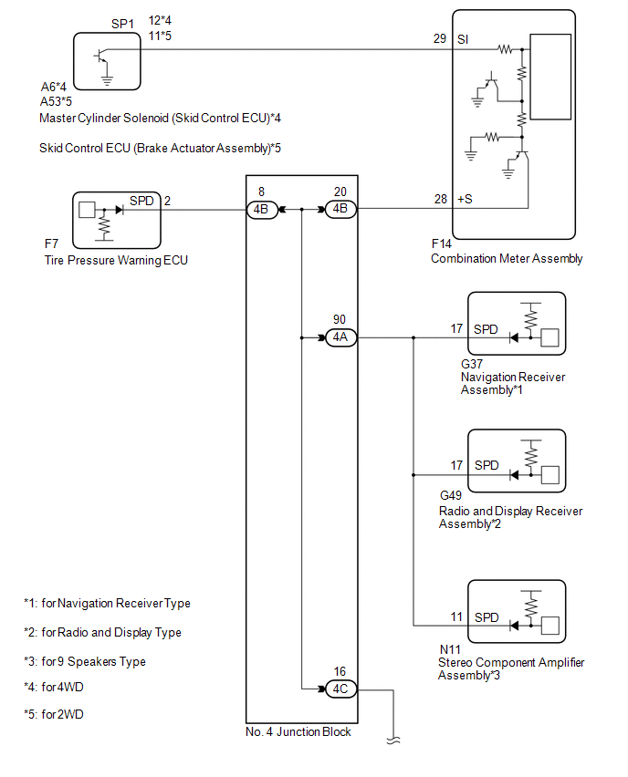
The vehicle speed signal consists of pulses sent to the combination meter assembly from the master cylinder solenoid (skid control ECU)*1 or skid control ECU (brake actuator assembly)*2.
- *1: for 4WD
- *2: for 2WD
WIRING DIAGRAM
.png)
PROCEDURE
|
1. |
CHECK ECU TERMINAL VOLTAGE (INPUT VOLTAGE) |
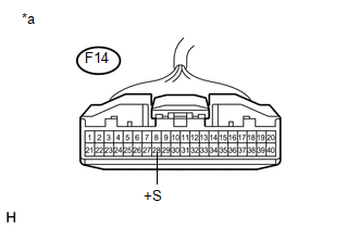
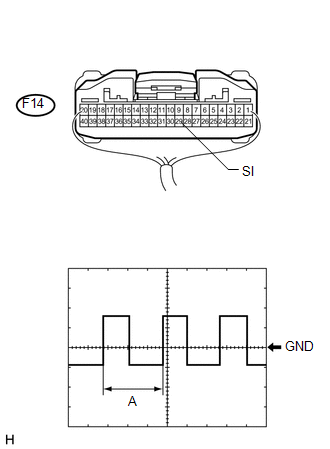
(a) Disconnect the F14 combination meter assembly connector.
|
(b) Measure the voltage according to the value(s) in the table below. Standard Voltage:
|
|
| NG | .gif) |
GO TO STEP 5 |
|
.gif)
|
2. |
CHECK COMBINATION METER ASSEMBLY (OUTPUT VOLTAGE) |
(a) for 4WD:
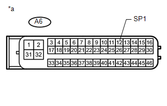
(1) Disconnect the A6 master cylinder solenoid (skid control ECU) connector.
|
(2) Measure the voltage according to the value(s) in the table below. Standard Voltage:
|
|
(b) for 2WD:
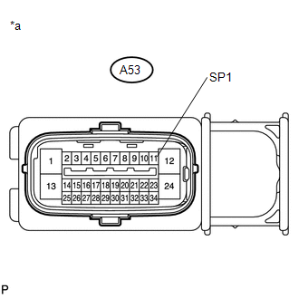
(1) Disconnect the A53 skid control ECU (brake actuator assembly) connector.
|
(2) Measure the voltage according to the value(s) in the table below. Standard Voltage:
|
|
| NG | |
GO TO STEP 4 |
|
|
3. |
CHECK COMBINATION METER ASSEMBLY (SPEED SIGNAL) |
|
(a) Check the input waveform. (1) Reconnect the F14 combination meter assembly connector. (2) Remove the combination meter assembly with the connector(s) still connected. (3) Connect an oscilloscope to terminal F14-29 (SI) and body ground. (4) Turn the ignition switch to ON. (5) Check the signal waveform according to the condition(s) in the table below. Measurement Condition
OK: The waveform displayed is as shown in the illustration. HINT: When the system is functioning normally, one wheel revolution generates 4 pulses. As the vehicle speed increases, the width indicated by (A) in the illustration narrows. |
|
|
Result |
Proceed to |
|---|---|
|
OK |
A |
|
NG (for 4WD) |
B |
|
NG (for 2WD) |
C |
| A | |
REPLACE COMBINATION METER ASSEMBLY |
| B | |
REPLACE MASTER CYLINDER SOLENOID (SKID CONTROL ECU) |
| C | |
REPLACE SKID CONTROL ECU (BRAKE ACTUATOR ASSEMBLY) |
|
4. |
CHECK HARNESS AND CONNECTOR (COMBINATION METER ASSEMBLY - SKID CONTROL ECU) |
(a) Disconnect the F14 combination meter assembly connector.
(b) Disconnect the A6 master cylinder solenoid (skid control ECU )*1 or A53 skid control ECU (brake actuator assembly)*2 connector.
(c) Measure the resistance according to the value(s) in the table below.
Standard Resistance:
|
Tester Connection |
Condition |
Specified Condition |
|---|---|---|
|
F14-29 (SI) - A6-12 (SP1)*1 F14-29 (SI) - A53-11 (SP1)*2 |
Always |
Below 1 Ω |
|
A6-12 (SP1) - Body ground*1 A53-11 (SP1) - Body ground*2 |
Always |
10 kΩ or higher |
- *1: for 4WD
- *2: for 2WD
| OK | |
REPLACE COMBINATION METER ASSEMBLY |
| NG | |
REPAIR OR REPLACE HARNESS OR CONNECTOR |
|
5. |
CHECK HARNESS AND CONNECTOR (COMBINATION METER ASSEMBLY - NO. 4 JUNCTION BLOCK) |
(a) Disconnect the F14 combination meter assembly connector.
(b) Disconnect the 4B No. 4 junction block connector.
(c) Measure the resistance according to the value(s) in the table below.
Standard Resistance:
|
Tester Connection |
Condition |
Specified Condition |
|---|---|---|
|
F14-28 (+S) - 4B-20 |
Always |
Below 1 Ω |
|
F14-28 (+S) - Body ground |
Always |
10 kΩ or higher |
| NG | |
REPAIR OR REPLACE HARNESS OR CONNECTOR |
|
|
6. |
CHECK HARNESS AND CONNECTOR (NO. 4 JUNCTION BLOCK) |
(a) Inspect for a short in the circuit that is connected to the junction block connector shown in the wiring diagram.
HINT:
If voltage is not present, it is possible that an ECU or circuit has a malfunction. The malfunctioning ECU or circuit will be diagnosed in the following steps.
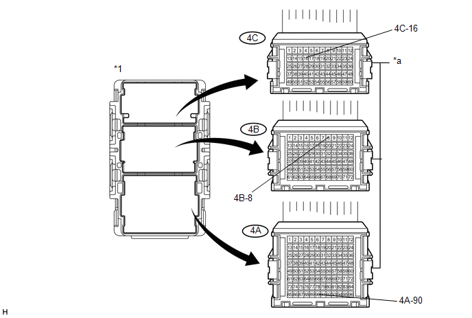
(1) Disconnect the 4A No. 4 junction block connector.
 Text in Illustration
|
*1 |
No. 4 Junction Block |
- |
- |
|
*a |
Front view of wire harness connector (to No. 4 Junction Block) |
- |
- |
(2) Disconnect the 4C No. 4 junction block connector.
(3) Measure the voltage according to the value(s) in the table below.
Standard Voltage:
|
Tester Connection |
Switch Condition |
Specified Condition |
|---|---|---|
|
4C-16 - Body ground |
Ignition switch ON |
4.5 to 14 V |
|
4B-8 - Body ground |
Ignition switch ON |
4.5 to 14 V |
|
4A-90 - Body ground |
Ignition switch ON |
4.5 to 14 V |
|
Result |
Proceed to |
|---|---|
|
Voltage is not present in one circuit |
A |
|
Voltage is present in all the circuits |
B |
| B | |
REPLACE NO. 4 JUNCTION BLOCK |
|
|
7. |
SYSTEM CHECK |
(a) Select the circuit for which voltage was not present in the previous step.
Result|
Tester Connection |
System that Uses the Circuit |
Proceed to |
|---|---|---|
|
4C-16 - Body ground |
SFI system, smart key system*1, safety connect system*2, voltage inverter*1, intuitive parking assist system*3 |
A |
|
4B-8 - Body ground |
Tire pressure warning system |
B |
|
4A-90 - Body ground |
Audio and visual system or navigation system |
C |
- *1: w/ Smart Key System
- *2: w/ Safety Connect System
- *3: w/ Intuitive Parking Assist System
| B | |
GO TO STEP 16 |
| C | |
GO TO STEP 17 |
|
|
8. |
CHECK HARNESS AND CONNECTOR (NO. 4 JUNCTION BLOCK - NO. 5 JUNCTION BLOCK) |
(a) Disconnect the 4C No. 4 junction block connector.
(b) Disconnect the 5B No. 5 junction block connector.
(c) Measure the resistance according to the value(s) in the table below.
Standard Resistance:
|
Tester Connection |
Condition |
Specified Condition |
|---|---|---|
|
4C-16 - 5B-25 |
Always |
Below 1 Ω |
|
4C-16 - Body ground |
Always |
10 kΩ or higher |
| NG | |
REPAIR OR REPLACE HARNESS OR CONNECTOR |
|
|
9. |
CHECK HARNESS AND CONNECTOR (NO. 5 JUNCTION BLOCK) |
(a) Disconnect the 5A No. 5 junction block connector.
(b) Measure the resistance according to the value(s) in the table below.
Standard Resistance:
|
Tester Connection |
Condition |
Specified Condition |
|---|---|---|
|
5B-2 - 5A-13 |
Always |
Below 1 Ω |
|
5B-2 - Body ground |
Always |
10 kΩ or higher |
| NG | |
REPAIR OR REPLACE HARNESS OR CONNECTOR |
|
|
10. |
CHECK HARNESS AND CONNECTOR (NO. 5 JUNCTION BLOCK) |
(a) Inspect for a short in the circuit that is connected to the junction block connector shown in the wiring diagram.
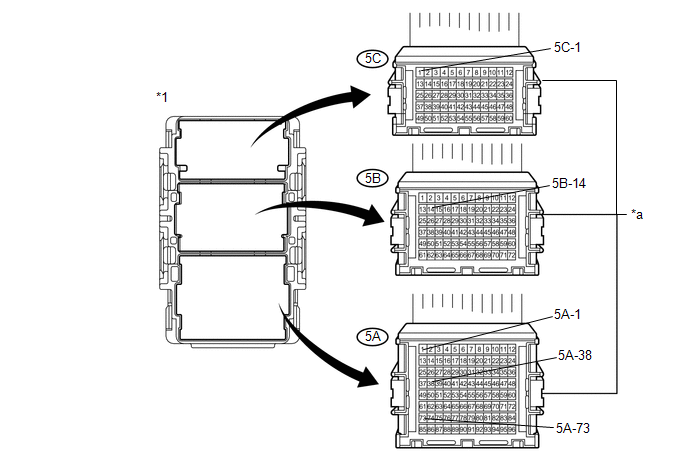
(1) Disconnect the 5C No. 5 junction block connector.
 Text in Illustration
|
*1 |
No. 5 Junction Block |
- |
- |
|
*a |
Front view of wire harness connector (to No. 5 Junction Block) |
- |
- |
(2) Measure the voltage according to the value(s) in the table below.
Standard Voltage:
|
Tester Connection |
Switch Condition |
Specified Condition |
|---|---|---|
|
5B-14 - Body ground |
Ignition switch ON |
4.5 to 14 V |
|
5C-1 - Body ground*1 |
Ignition switch ON |
4.5 to 14 V |
|
5A-1 - Body ground*1 |
Ignition switch ON |
4.5 to 14 V |
|
5A-38 - Body ground*2 |
Ignition switch ON |
4.5 to 14 V |
|
5A-73 - Body ground*3 |
Ignition switch ON |
4.5 to 14 V |
- *1: w/ Smart Key System
- *2: w/ Safety Connect System
- *3: w/ Intuitive Parking Assist System
|
Result |
Proceed to |
|---|---|
|
Voltage is not present in one circuit |
A |
|
Voltage is present in all the circuits |
B |
| B | |
REPLACE NO. 5 JUNCTION BLOCK |
|
|
11. |
SYSTEM CHECK |
(a) Select the circuit for which voltage was not present in the previous step.
Result|
Tester Connection |
System that Uses the Circuit |
Proceed to |
|---|---|---|
|
5B-14 - Body ground |
SFI system |
A |
|
5C-1 - Body ground*1 |
Voltage inverter |
B |
|
5A-1 - Body ground*1 |
Smart key system |
C |
|
5A-38 - Body ground*2 |
Safety connect system |
D |
|
5A-73 - Body ground*3 |
Intuitive Parking Assist System |
E |
- *1: w/ Smart Key System
- *2: w/ Safety Connect System
- *3: w/ Intuitive Parking Assist System
| B | |
GO TO STEP 13 |
| C | |
GO TO STEP 14 |
| D | |
GO TO STEP 15 |
| E | |
GO TO STEP 20 |
|
|
12. |
CHECK HARNESS AND CONNECTOR (ECM CIRCUIT) |
(a) Disconnect the F51 ECM connector.
(b) Measure the resistance according to the value(s) in the table below.
Standard Resistance:
|
Tester Connection |
Condition |
Specified Condition |
|---|---|---|
|
F51-18 (SPD) - Body ground |
Always |
10 kΩ or higher |
| OK | |
REPLACE ECM |
| NG | |
REPAIR OR REPLACE HARNESS OR CONNECTOR |
|
13. |
CHECK HARNESS AND CONNECTOR (VOLTAGE INVERTER ASSEMBLY CIRCUIT) |
(a) Disconnect the N19 voltage inverter assembly connector.
(b) Measure the resistance according to the value(s) in the table below.
Standard Resistance:
|
Tester Connection |
Condition |
Specified Condition |
|---|---|---|
|
N19-2 (SPD) - Body ground |
Always |
10 kΩ or higher |
| OK | |
REPLACE VOLTAGE INVERTER ASSEMBLY |
| NG | |
REPAIR OR REPLACE HARNESS OR CONNECTOR |
|
14. |
CHECK HARNESS AND CONNECTOR (POWER MANAGEMENT CONTROL ECU CIRCUIT) |
(a) Disconnect the F80 power management control ECU connector.
(b) Measure the resistance according to the value(s) in the table below.
Standard Resistance:
|
Tester Connection |
Condition |
Specified Condition |
|---|---|---|
|
F80-23 (SPD) - Body ground |
Always |
10 kΩ or higher |
| OK | |
REPLACE POWER MANAGEMENT CONTROL ECU |
| NG | |
REPAIR OR REPLACE HARNESS OR CONNECTOR |
|
15. |
CHECK HARNESS AND CONNECTOR (TELEMATICS TRANSCEIVER CIRCUIT) |
(a) Disconnect the F39 telematics transceiver connector.
(b) Measure the resistance according to the value(s) in the table below.
Standard Resistance:
|
Tester Connection |
Condition |
Specified Condition |
|---|---|---|
|
F39-10 (SPDP) - Body ground |
Always |
10 kΩ or higher |
| OK | |
REPLACE TELEMATICS TRANSCEIVER |
| NG | |
REPAIR OR REPLACE HARNESS OR CONNECTOR |
|
16. |
CHECK HARNESS AND CONNECTOR (TIRE PRESSURE WARNING ECU CIRCUIT) |
(a) Disconnect the F7 tire pressure warning ECU connector.
(b) Measure the resistance according to the value(s) in the table below.
Standard Resistance:
|
Tester Connection |
Condition |
Specified Condition |
|---|---|---|
|
F7-2 (SPD) - Body ground |
Always |
10 kΩ or higher |
| OK | |
REPLACE TIRE PRESSURE WARNING ECU |
| NG | |
REPAIR OR REPLACE HARNESS OR CONNECTOR |
|
17. |
SYSTEM CHECK |
(a) Proceed to the appropriate inspection based on the components of the vehicle.
Component|
Component |
Proceed to |
|---|---|
|
for Navigation Receiver Type |
A |
|
for Radio and Display Type |
B |
|
for 9 Speakers Type |
C |
| B | |
GO TO STEP 19 |
| C | |
GO TO STEP 21 |
|
|
18. |
CHECK HARNESS AND CONNECTOR (NAVIGATION RECEIVER CIRCUIT) |
(a) Disconnect the G37 navigation receiver connector.
(b) Measure the resistance according to the value(s) in the table below.
Standard Resistance:
|
Tester Connection |
Switch Condition |
Specified Condition |
|---|---|---|
|
G37-17 (SPD) - Body ground |
Always |
10 kΩ or higher |
| OK | |
REPLACE NAVIGATION RECEIVER ASSEMBLY |
| NG | |
REPAIR OR REPLACE HARNESS AND CONNECTOR |
|
19. |
CHECK HARNESS AND CONNECTOR (RADIO AND DISPLAY RECEIVER CIRCUIT) |
(a) Disconnect the G49 radio and display receiver connector.
(b) Measure the resistance according to the value(s) in the table below.
Standard Resistance:
|
Tester Connection |
Switch Condition |
Specified Condition |
|---|---|---|
|
G49-17 (SPD) - Body ground |
Always |
10 kΩ or higher |
| OK | |
REPLACE RADIO AND DISPLAY RECEIVER ASSEMBLY |
| NG | |
REPAIR OR REPLACE HARNESS OR CONNECTOR |
|
20. |
CHECK HARNESS AND CONNECTOR (CLEARANCE WARNING ECU CIRCUIT) |
(a) Disconnect the F95 clearance warning ECU connector.
(b) Measure the resistance according to the value(s) in the table below.
Standard Resistance:
|
Tester Connection |
Condition |
Specified Condition |
|---|---|---|
|
F95-5 (SPD) - Body ground |
Always |
10 kΩ or higher |
| OK | |
REPLACE CLEARANCE WARNING ECU ASSEMBLY |
| NG | |
REPAIR OR REPLACE HARNESS OR CONNECTOR |
|
21. |
CHECK HARNESS AND CONNECTOR (STEREO COMPONENT AMPLIFIER ASSEMBLY) |
(a) Disconnect the N11 stereo component amplifier connector.
(b) Measure the resistance according to the value(s) in the table below.
Standard Resistance:
|
Tester Connection |
Condition |
Specified Condition |
|---|---|---|
|
N11-11 (SPD) - Body ground |
Always |
10 kΩ or higher |
| OK | |
REPLACE STEREO COMPONENT AMPLIFIER ASSEMBLY |
| NG | |
REPAIR OR REPLACE HARNESS OR CONNECTOR |
 Meter Illumination is Always Dark
DESCRIPTION
This inspection is only for vehicles with automatic light control.
The meter CPU receives signals from this circuit to adjust the illumination of
the meter, instrument panel and access ...
 Mirror (int)
...
Other materials about Toyota 4Runner:
Lost Communication with ECM (U0100,U0142,U0155)
DESCRIPTION
The air conditioning amplifier communicates with the ECM, main body ECU (multiplex
network body ECU) and combination meter through the CAN communication system.
DTC Code
DTC Detection Condition
Trouble Area
...
Antenna location and effective range
Antenna location
1. Antennas outside the cabin
2. Antennas inside the cabin
3. Antenna outside the luggage compartment
Effective range (areas within which the electronic key is detected)
When locking or unlocking the
doors
The system can be opera ...

0.027