Toyota 4Runner: Meter Illumination is Always Dark
DESCRIPTION
This inspection is only for vehicles with automatic light control.
The meter CPU receives signals from this circuit to adjust the illumination of the meter, instrument panel and accessory meter assembly. The meter CPU sets the illumination level based on the user operation of the light control rheostat.
HINT:
- The meter illumination level can be adjusted by rotating the light control rheostat dial up and down.
- The meter illumination dims when the light control switch is turned to the tail or head position at night.
- Setting the meter illumination to maximum brightness cancels the above dimming of the meter illumination.
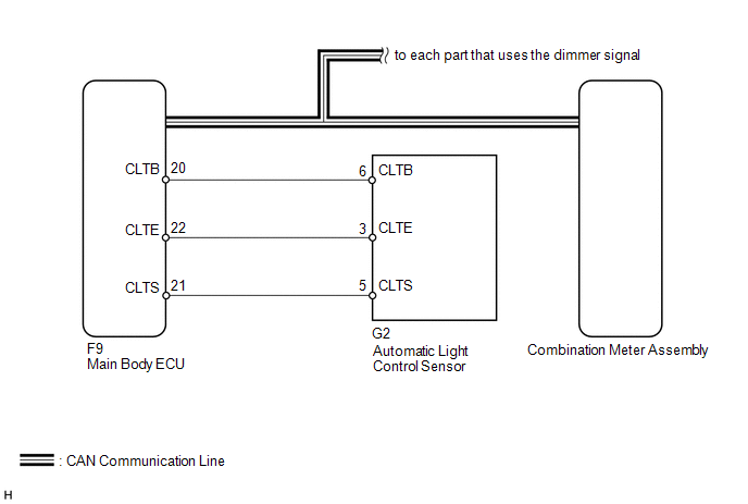
WIRING DIAGRAM
CAUTION / NOTICE / HINT
HINT:
Setting the meter illumination to minimum brightness turns off the meter illumination when the light control switch is changed to the tail or head position, or changed to the AUTO position at night.
PROCEDURE
|
1. |
CHECK CAN COMMUNICATION SYSTEM |
(a) Check if a CAN communication DTC is output (See page
.gif) ).
).
Result
|
Result |
Proceed to |
|---|---|
|
CAN communication DTC is not output |
A |
|
CAN communication DTC is output |
B |
| B | .gif) |
GO TO CAN COMMUNICATION SYSTEM |
|
.gif)
|
2. |
CHECK DTC (LIGHT SENSOR CIRCUIT) |
(a) Check if DTC B1244 is output (See page ).
Result
|
Result |
Proceed to |
|---|---|
|
B1244 is not output |
A |
|
B1244 is output |
B |
| B | |
GO TO LIGHTING SYSTEM |
|
|
3. |
CHECK OPERATION (HEATER CONTROL PANEL) |
(a) Turn the ignition switch to ON.
(b) Turn the light control switch to the tail, head or AUTO position.
(c) Cover the automatic light control sensor.
(d) Check the heater control panel illumination.
Result|
Result |
Proceed to |
|---|---|
|
Heater control panel illumination does not operate normally |
A |
|
Heater control panel illumination operates normally |
B |
HINT:
Both the heater control panel and combination meter assembly illumination dim according to the dimmer signal. Therefore, when only the meter illumination is always dark, there may be a malfunction in the combination meter assembly.
| B | |
REPLACE COMBINATION METER ASSEMBLY |
|
|
4. |
CHECK OPERATION (AUTOMATIC LIGHT CONTROL SYSTEM) |
(a) Turn the ignition switch to ON.
(b) Turn the light control switch to the AUTO position.
(c) Cover the automatic light control sensor.
(d) Check the taillights and low beam headlights.
OK:
The taillights and low beam headlights come on.
(e) Uncover the automatic light control sensor.
(f) Check the low beam headlights and taillights.
OK:
The taillights and low beam headlights go off.
Result|
Result |
Proceed to |
|---|---|
|
Automatic light control system operates normally |
A |
|
Automatic light control system does not operate normally |
B |
| B | |
GO TO LIGHTING SETTING |
|
|
5. |
REPLACE MAIN BODY ECU |
(a) Replace the main body ECU with a new or normally functioning one (See page
).
OK:
The operation of the combination meter assembly returns to normal.
HINT:
The meter CPU controls the meter illumination based on an auto dimmer signal from the main body ECU. When the meter illumination is always dark (very dim), it may be due to the main body ECU sending an auto dimmer signal to the meter CPU because of a malfunction in the main body ECU.
| OK | |
END |
| NG | |
REPLACE COMBINATION METER ASSEMBLY |
 Meter Illumination does not Dim at Night
DESCRIPTION
If the dimmer switch is turned to TAIL, HEAD or AUTO, the main body ECU sends
a TAIL relay signal, panel light illumination signal, panel relay signal and TAIL
cancel OFF signal to th ...
 Speed Signal Circuit
DESCRIPTION
The vehicle speed signal consists of pulses sent to the combination meter assembly
from the master cylinder solenoid (skid control ECU)*1 or skid control ECU (brake
actuator assembly) ...
Other materials about Toyota 4Runner:
Lost Communication with ECM / PCM "A" (U0100,U0126,U0129)
DESCRIPTION
The power steering ECU assembly receives signals from the ECM, steering angle
sensor and master cylinder solenoid (skid control ECU) via the CAN communication
system.
DTC Code
DTC Detection Condition
Trouble A ...
Inspection
INSPECTION
PROCEDURE
1. INSPECT FRONT SHOCK ABSORBER ASSEMBLY LH
(a) Compress and extend the shock absorber rod and check that there is no abnormal
resistance or unusual sound during operation.
If there is any abnormality, replace the front shock absorbe ...

0.0163