Toyota 4Runner: Installation
INSTALLATION
PROCEDURE
1. INSTALL WINDSHIELD WASHER MOTOR AND PUMP ASSEMBLY
(a) Install the windshield washer motor and pump assembly to the packing of the washer jar.
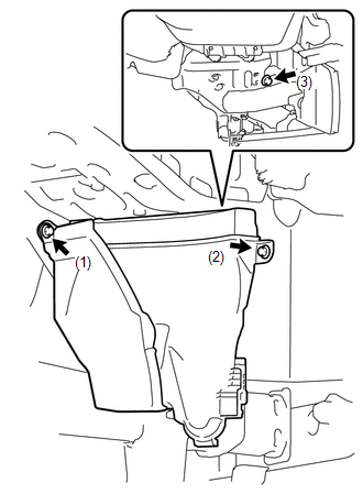
2. INSTALL WASHER JAR
|
(a) Attach the guide to install the washer jar, and then install the 3 screws. HINT: Tighten the screws in the order shown in the illustration. Torque: 5.5 N·m {56 kgf·cm, 49 in·lbf} |
|
3. INSTALL WASHER INLET SUB-ASSEMBLY
(a) Install the clip to the washer inlet sub-assembly.
4. FILL WINDSHIELD WASHER FLUID
(a) Connect the washer hose to the hose of the windshield washer motor and pump assembly and fill the washer jar with windshield washer fluid.
5. INSTALL FRONT FENDER LINER RH
(See page .gif) )
)
6. INSTALL FRONT BUMPER COVER (w/ Intuitive Parking Assist System)
(See page )
7. INSTALL FRONT BUMPER COVER (w/o Intuitive Parking Assist System)
(See page )
8. CONNECT CABLE TO NEGATIVE BATTERY TERMINAL
NOTICE:
When disconnecting the cable, some systems need to be initialized after the cable
is reconnected (See page ).
9. ADJUST FOG LIGHT AIMING
(See page )
 Inspection
INSPECTION
PROCEDURE
1. INSPECT WINDSHIELD WASHER MOTOR AND PUMP ASSEMBLY
(a) Remove the washer jar.
(b) Disconnect the windshield washer motor and pump connector.
HINT:
Make sure that the winds ...
 Washer Motor(for Rear Side)
Components
COMPONENTS
ILLUSTRATION
Removal
REMOVAL
PROCEDURE
1. DISCONNECT CABLE FROM NEGATIVE BATTERY TERMINAL
NOTICE:
When disconnecting the cable, some systems need to be initialized ...
Other materials about Toyota 4Runner:
Installation
INSTALLATION
PROCEDURE
1. INSTALL VANE PUMP ASSEMBLY
(a) Install the vane pump with the 2 bolts.
Torque:
43 N·m {438 kgf·cm, 32 ft·lbf}
(b) Install the wire harness bracket with the bolt.
Torque:
43 N·m {438 kgf·cm, 32 ft·lbf}
2. CONNECT NO. 1 ...
Reassembly
REASSEMBLY
CAUTION / NOTICE / HINT
CAUTION:
Wear protective gloves. Sharp areas on the parts may injure your hands.
PROCEDURE
1. INSTALL FRONT SEAT SIDE AIRBAG ASSEMBLY
2. INSTALL SEPARATE TYPE FRONT SEATBACK COVER
(a) Using hog ring plier ...

0.0271