Toyota 4Runner: SRS Warning Light Remains ON
DESCRIPTION
The SRS warning light is located in the combination meter.
When the SRS is normal, the SRS warning light comes on for approximately 6 seconds after the ignition switch is turned from off to ON, and then goes off automatically.
If there is a malfunction in the SRS, the SRS warning light comes on to inform the driver of a problem.
When terminals TC and CG of the DLC3 are connected, DTCs are output by the blinking of the SRS warning light.
The SRS is equipped with a voltage-increase circuit (DC-DC converter) in the center airbag sensor in case the source voltage drops.
When the battery voltage drops, the voltage-increase circuit (DC-DC converter) functions to increase the voltage of the SRS to normal voltage.
A malfunction in this circuit is not recorded in the center airbag sensor. The SRS warning light automatically goes off when the source voltage returns to normal.
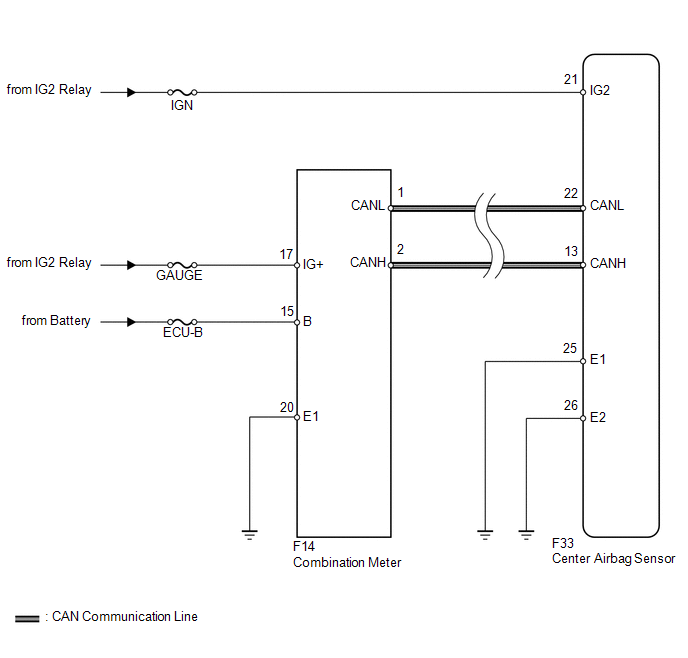
The signal to illuminate the SRS warning light is transmitted from the center airbag sensor to the combination meter through the CAN communication system.
WIRING DIAGRAM
CAUTION / NOTICE / HINT
NOTICE:
When disconnecting the cable from the negative (-) battery terminal while performing
repairs, some systems need to be initialized after the cable is reconnected (See
page .gif) ).
).
PROCEDURE
|
1. |
CHECK CAN COMMUNICATION SYSTEM |
(a) Check if a CAN communication DTC is output (See page
).
Result
|
Result |
Proceed to |
|---|---|
|
DTC is not output |
A |
|
DTCs are output |
B |
| B | .gif) |
REPAIR CIRCUITS INDICATED BY OUTPUT DTCS |
|
.gif)
|
2. |
CHECK BATTERY |
(a) Measure the voltage of the battery.
Standard voltage:
11 to 14 V
| NG | |
REPLACE OR RECHARGE BATTERY |
|
|
3. |
CHECK CONNECTORS |
(a) Turn the ignition switch off.
(b) Disconnect the cable from the negative (-) battery terminal, and wait for at least 90 seconds.
(c) Check that the connectors are properly connected to the center airbag sensor and combination meter.
OK:
The connectors are properly connected.
| NG | |
CONNECT CONNECTORS PROPERLY |
|
|
4. |
CHECK HARNESS AND CONNECTOR (SOURCE VOLTAGE OF CENTER AIRBAG SENSOR) |
|
(a) Disconnect the connectors from the center airbag sensor. |
|
(b) Connect the cable to the negative (-) battery terminal, and wait for at least 2 seconds.
(c) Turn the ignition switch to ON.
(d) Operate all the components of the electrical system (defogger, wipers, headlights, heater blower, etc.).
(e) Measure the voltage according to the value(s) in the table below.
Standard Voltage:
|
Tester Connection |
Switch Condition |
Specified Condition |
|---|---|---|
|
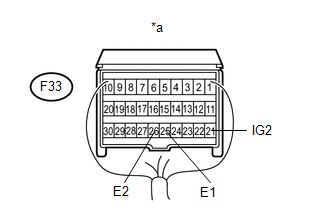
F33-21 (IG2) - F33-25 (E1) |
Ignition switch ON |
11 to 14 V |
|
F33-21 (IG2) - F33-26 (E2) |
Ignition switch ON |
11 to 14 V |
|
*a |
Rear view of wire harness connector (to Center Airbag Sensor) |
| NG | |
REPLACE INSTRUMENT PANEL WIRE |
|
|
5. |
CHECK HARNESS AND CONNECTOR (SOURCE VOLTAGE OF COMBINATION METER) |
|
(a) Disconnect the cable from the negative (-) battery terminal, and wait for at least 90 seconds. |
|
(b) Disconnect the F14 connector from the combination meter.
(c) Connect the cable to the negative (-) battery terminal, and wait for at least 2 seconds.
(d) Measure the voltage according to the value(s) in the table below.
Standard Voltage:
|
Tester Connection |
Switch Condition |
Specified Condition |
|---|---|---|
|
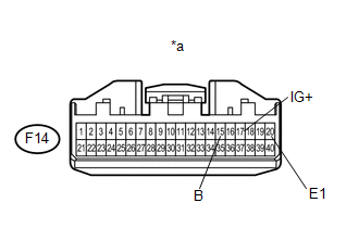
F14-17 (IG+) - F14-20 (E1) |
Ignition switch ON |
11 to 14 V |
|
F14-15 (B) - F14-20 (E1) |
Always |
11 to 14 V |
|
*a |
Front view of wire harness connector (to Combination Meter) |
| NG | |
REPAIR OR REPLACE HARNESS OR CONNECTOR |
|
|
6. |
CHECK SRS WARNING LIGHT (SHORT TO GROUND) |
(a) Turn the ignition switch off.
(b) Disconnect the cable from the negative (-) battery terminal, and wait for at least 90 seconds.
(c) Connect the connector to the combination meter.
(d) Connect the cable to the negative (-) battery terminal, and wait for at least 2 seconds.
(e) Turn the ignition switch to ON.
(f) Check the SRS warning light condition.
NOTICE:
Make sure that nobody is in the vehicle.
OK:
After the primary check period, the SRS warning light goes off for approximately 10 seconds and then remains on.
HINT:
The primary check period is approximately 6 seconds after the ignition switch is turned to ON.
| OK | |
REPLACE CENTER AIRBAG SENSOR ASSEMBLY |
| NG | |
GO TO METER / GAUGE SYSTEM |
 Passenger Airbag ON/OFF Indicator Circuit Malfunction (B1660/43)
DESCRIPTION
The passenger airbag ON/OFF indicator circuit consists of the airbag sensor assembly
and passenger airbag ON/OFF indicator.
The passenger airbag ON/OFF indicator indicates the operatio ...
 SRS Warning Light does not Come ON
DESCRIPTION
Refer to "SRS Warning Light Remains ON" (See page
).
WIRING DIAGRAM
Refer to "SRS Warning Light Remains ON" (See page
).
CAUTION / NOTICE / HINT
NOTICE:
When ...
Other materials about Toyota 4Runner:
Installation
INSTALLATION
PROCEDURE
1. INSTALL OCCUPANT CLASSIFICATION ECU
(a) Attach the claw to install the occupant classification ECU.
NOTICE:
If the occupant classification ECU has been dropped, or there are any
cracks, dents or other defects i ...
Components
COMPONENTS
ILLUSTRATION
ILLUSTRATION
ILLUSTRATION
ILLUSTRATION
ILLUSTRATION
ILLUSTRATION
ILLUSTRATION
ILLUSTRATION
ILLUSTRATION
ILLUSTRATION
...

0.0175