Toyota 4Runner: Installation
INSTALLATION
PROCEDURE
1. INSTALL OCCUPANT CLASSIFICATION ECU
|
(a) Attach the claw to install the occupant classification ECU. NOTICE: If the occupant classification ECU has been dropped, or there are any cracks, dents or other defects in the case or connector, replace the occupant classification ECU with a new one. |
|
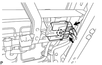
(b) Connect the 2 connectors.
NOTICE:
When installing the occupant classification ECU, be careful that the SRS wiring does not interfere with other parts and that it is not pinched between other parts.
2. INSTALL FRONT SEAT ASSEMBLY RH
HINT:
Refer to the procedure from Install Front Seat Assembly (See page
.gif) ).
).
3. ZERO POINT CALIBRATION AND SENSITIVITY CHECK
(a) Perform zero point calibration and the sensitivity check (See page
).
4. PERFORM DIAGNOSTIC SYSTEM CHECK
(a) Perform a diagnostic system check (See page
).
5. CHECK SRS WARNING LIGHT
(a) Check the SRS warning light (See page ).
 On-vehicle Inspection
ON-VEHICLE INSPECTION
CAUTION / NOTICE / HINT
CAUTION:
Be sure to follow the correct removal and installation procedures for the occupant
classification ECU.
PROCEDURE
1. CHECK OCCUPANT CLASSIF ...
 Removal
REMOVAL
PROCEDURE
1. PRECAUTION
CAUTION:
Be sure to read Precaution thoroughly before servicing (See page
).
NOTICE:
When removing the front seat assembly RH, perform zero point calibr ...
Other materials about Toyota 4Runner:
Dtc Check / Clear
DTC CHECK / CLEAR
1. DTC CHECK / CLEAR (when Using Techstream)
(a) Check for DTCs.
(1) Connect the Techstream to the DLC3.
(2) Turn the ignition switch to ON.
(3) Turn the Techstream on.
(4) Enter the following menus: Chassis / ABS/VSC/TRAC / Trouble Cod ...
If the shift lever cannot be shifted from P
If the shift lever cannot be shifted with your foot on the brake pedal,
there may be a problem with the shift lock system (a system to prevent
accidental operation of the shift lever). Have the vehicle inspected by your
Toyota dealer immediately.
The fo ...

0.0138