Toyota 4Runner: Traction Off Switch
Components
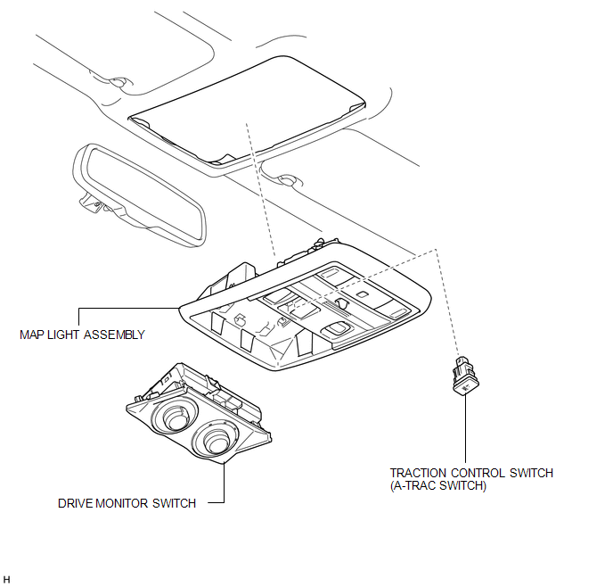
COMPONENTS
ILLUSTRATION
Removal
REMOVAL
PROCEDURE
1. REMOVE DRIVE MONITOR SWITCH
.gif)
2. REMOVE MAP LIGHT ASSEMBLY
|
(a) Remove the screws. |
|
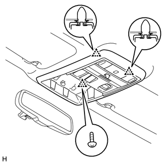
(b) Detach the 2 clips and remove the map light assembly.
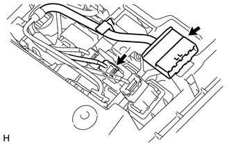
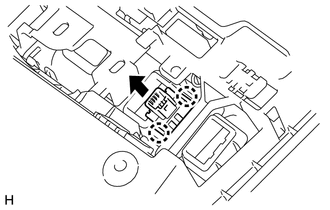
3. REMOVE TRACTION CONTROL SWITCH (A-TRAC SWITCH)
|
(a) Disconnect the 2 connectors. |
|
|
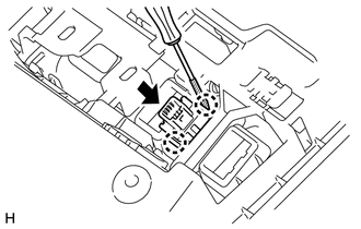
(b) Using a screwdriver, detach the 2 claws and remove the traction control switch (A-TRAC switch) from the map light assembly. HINT: Tape the screwdriver tip before use. |
|
Inspection
INSPECTION
PROCEDURE
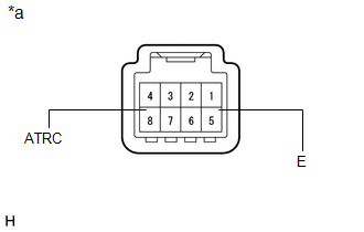
1. INSPECT TRACTION CONTROL SWITCH (A-TRAC SWITCH)
|
(a) Measure the resistance according to the value(s) in the table below. Standard Resistance:
If the result is not as specified, replace the traction control switch (A-TRAC switch). |
|
Installation
INSTALLATION
PROCEDURE
1. INSTALL TRACTION CONTROL SWITCH (A-TRAC SWITCH)
|
(a) Attach the 2 claws to install the traction control switch (A-TRAC switch) to the map light assembly. |
|
(b) Connect the 2 connectors.
2. INSTALL MAP LIGHT ASSEMBLY
(a) Attach the 2 clips to install the map light assembly.
(b) Install the screws.
3. INSTALL DRIVE MONITOR SWITCH
.gif)
 Steering Angle Sensor
Components
COMPONENTS
ILLUSTRATION
Removal
REMOVAL
PROCEDURE
1. PLACE FRONT WHEELS FACING STRAIGHT AHEAD
2. DISCONNECT CABLE FROM NEGATIVE BATTERY TERMINAL
CAUTION:
Wait at least 90 sec ...

Other materials about Toyota 4Runner:
Washer Nozzle(for Rear Side)
Components
COMPONENTS
ILLUSTRATION
On-vehicle Inspection
ON-VEHICLE INSPECTION
CAUTION / NOTICE / HINT
HINT:
The washer fluid does not spray if the back door and back door glass are not
closed.
PROCEDURE
1. INSPECT REAR WASHER NOZZLE
(a) With ...
Seat Memory Switch
Components
COMPONENTS
ILLUSTRATION
Removal
REMOVAL
PROCEDURE
1. REMOVE FRONT DOOR LOWER FRAME BRACKET GARNISH LH
2. REMOVE NO. 2 DOOR INSIDE HANDLE BEZEL LH
3. REMOVE FRONT DOOR TRIM BOARD SUB-ASSEMBLY LH
4. REMOVE FRONT DOOR INNER GLAS ...

0.0177