Toyota 4Runner: LIN Communication Master Malfunction (B2287,B278C)
DESCRIPTION
- DTC B2287 is stored when there is an open or short circuit or an ECU communication malfunction between the power management control ECU and certification ECU.
- DTC B278C is stored when LIN communication between the certification ECU and power management control ECU stops for 10 seconds or more.
|
DTC Code |
DTC Detection Condition |
Trouble Area |
|---|---|---|
|
B2287 |
There is an open or short circuit or an ECU communication malfunction between the power management control ECU and certification ECU. |
|
|
B278C |
No communication between the certification ECU and power management control ECU for 10 seconds or more. |
|
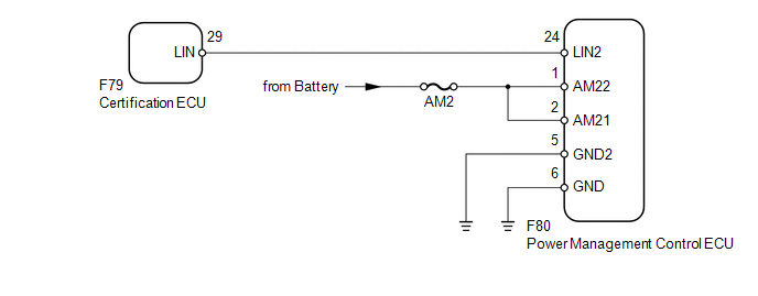
WIRING DIAGRAM
CAUTION / NOTICE / HINT
NOTICE:
- When using the Techstream with the ignition switch off to troubleshoot:
Connect the Techstream to the vehicle and turn a courtesy light switch on and off at 1.5 second intervals until communication between the Techstream and vehicle begins.
- Inspect the fuses and bulbs for circuits related to this system before performing the following inspection procedure.
HINT:
When DTC B2287, B278C and B2785 are output simultaneously, perform troubleshooting
for DTC B2785 first (See page .gif) ).
).
PROCEDURE
|
1. |
CLEAR DTC |
(a) Clear the DTCs (See page ).
|
.gif)
|
2. |
CHECK FOR DTC |
(a) Check for DTCs (See page ).
OK:
DTC B2287 or B278C is not output.
| OK | .gif) |
USE SIMULATION METHOD TO CHECK |
|
|
3. |
CHECK HARNESS AND CONNECTOR (CERTIFICATION ECU - POWER MANAGEMENT CONTROL ECU) |
(a) Disconnect the F79 certification ECU connector.
(b) Disconnect the F80 power management control ECU connector.
(c) Measure the resistance according to the value(s) in the table below.
Standard Resistance:
|
Tester Connection |
Condition |
Specified Condition |
|---|---|---|
|
F79-29 (LIN) - F80-24 (LIN2) |
Always |
Below 1 Ω |
|
F79-29 (LIN) or F80-24 (LIN2) - Body ground |
Always |
10 kΩ or higher |
| NG | |
REPAIR OR REPLACE HARNESS OR CONNECTOR |
|
|
4. |
CHECK HARNESS AND CONNECTOR (POWER MANAGEMENT CONTROL ECU - BATTERY AND BODY GROUND) |
|
(a) Disconnect the F80 power management control ECU connector. |
|
(b) Measure the resistance according to the value(s) in the table below.
Standard Resistance:
|
Tester Connection |
Condition |
Specified Condition |
|---|---|---|
|
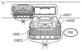
F80-5 (GND2) - Body ground |
Always |
Below 1 Ω |
|
F80-6 (GND) - Body ground |
Always |
Below 1 Ω |
(c) Measure the voltage according to the value(s) in the table below.
Standard Voltage:
|
Tester Connection |
Condition |
Specified Condition |
|---|---|---|
|
F80-1 (AM22) - Body ground |
Always |
11 to 14 V |
|
F80-2 (AM21) - Body ground |
Always |
11 to 14 V |
|
*a |
Rear view of wire harness connector (to Power Management Control ECU) |
| NG | |
REPAIR OR REPLACE HARNESS OR CONNECTOR |
|
|
5. |
REPLACE POWER MANAGEMENT CONTROL ECU |
(a) Temporarily replace the power management control ECU with a new or normally
functioning one (See page ).
|
|
6. |
CLEAR DTC |
(a) Clear the DTCs (See page ).
|
|
7. |
CHECK FOR DTC |
(a) Check for DTCs (See page ).
OK:
DTC B2287 or B278C is not output.
| OK | |
END (POWER MANAGEMENT CONTROL ECU IS DEFECTIVE) |
| NG | |
REPLACE CERTIFICATION ECU |
 Rear Door LH ECU Communication Stop (B2324)
DESCRIPTION
This DTC is stored when LIN communication between the rear power window regulator
motor assembly LH and main body ECU (multiplex network body ECU) stops for 10 seconds
or more.
...
 Back Door ECU Communication Stop (B1287)
DESCRIPTION
This DTC is stored when LIN communication between the multiplex network door
ECU (back door P/W) and main body ECU (multiplex network body ECU) stops for 10
seconds or more.
...
Other materials about Toyota 4Runner:
Using the audio control function
Changing sound quality modes
Type A
Pressing selects the mode to be
changed in the following order:
“BAS”→“TRE”→“FAD”→“BAL”→“ASL”
Type B and C Press
.
Press
,
,
,
or
(type C only) as corresponds to
the desired mod ...
Installation
INSTALLATION
PROCEDURE
1. INSTALL VOLTAGE INVERTER ASSEMBLY
(a) Install the voltage inverter with the 3 bolts.
Torque:
7.5 N·m {76 kgf·cm, 66 in·lbf}
(b) Connect the 2 connectors.
2. INSTALL DECK TRIM SIDE PANEL ASSEMBLY RH
3. INSTALL FRONT DECK ...

0.0272