Toyota 4Runner: System Diagram
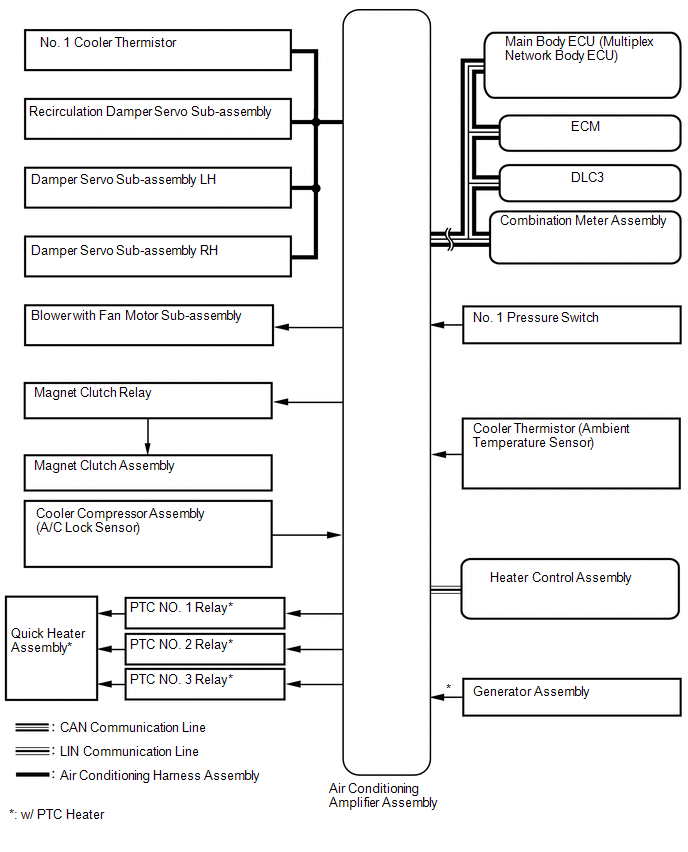
SYSTEM DIAGRAM
 Communication Table
|
Transmitter |
Receiver |
Signal |
Communication Line |
|---|---|---|---|
|
Air conditioning amplifier assembly |
ECM |
A/C idle up request signal |
CAN |
|
Heater idle up request signal |
|||
|
PTC heater control request signal* |
|||
|
Electricity load at low voltage state signal |
|||
|
Ambient temperature signal |
|||
|
Main body ECU |
Air conditioning amplifier assembly |
Main body request signal |
|
|
Combination meter assembly |
Air conditioning amplifier assembly |
Vehicle speed signal |
|
|
ECM |
Air conditioning amplifier assembly |
Engine coolant temperature signal |
|
|
Engine speed data |
|||
|
Engine type information signal |
|||
|
Heater control assembly |
Air conditioning amplifier assembly |
OFF operation switch signal |
LIN |
|
A/C switch signal |
|||
|
Rear defogger operation switch signal |
|||
|
Mode operation switch signal |
|||
|
REC/FRS switch signal |
|||
|
Set temperature switch signal |
|||
|
Blower operation switch signal |
- *: w/ PTC Heater
 System Description
SYSTEM DESCRIPTION
1. GENERAL
(a) The air conditioning system has the following controls.
Control
Outline
Manual Control
The air conditioning ampli ...
 How To Proceed With Troubleshooting
CAUTION / NOTICE / HINT
HINT:
Use these procedures to troubleshoot the air conditioning system.
*: Use the Techstream.
PROCEDURE
1.
VEHICLE BROUGHT TO W ...
Other materials about Toyota 4Runner:
Headlight (HI-BEAM) Circuit
DESCRIPTION
The main body ECU (multiplex network body ECU) receives headlight dimmer switch
information signals, and illuminates the high beam headlight.
WIRING DIAGRAM
CAUTION / NOTICE / HINT
NOTICE:
Inspect the fuses and bulbs for circuits related t ...
Dtc Check / Clear
DTC CHECK / CLEAR
NOTICE:
When the diagnosis system is changed from normal mode to check mode or vice versa,
all DTCs and freeze frame data recorded in normal mode are cleared. Before changing
modes, always check and make a note of DTCs and freeze frame ...

0.0203