Toyota 4Runner: System Description
SYSTEM DESCRIPTION
1. PUSH-BUTTON START DESCRIPTION
(a) The push-button start function uses a push-type engine switch, which the driver can operate by merely carrying the key. This system consists primarily of the power management control ECU, engine switch, ID code box, steering lock ECU, key, ACC relay, IG1 relay, IG2 relay and certification ECU. The power management control ECU controls the system. This function operates in cooperation with the smart key system.
2. FUNCTION OF COMPONENT
|
Component |
Function |
|---|---|
|
Engine switch - Transponder key amplifier |
Informs the driver of a power source mode or system abnormality with the illumination state of the indicator light. |
|
Power management control ECU |
|
|
Certification ECU |
|
|
Stop light switch |
Outputs the state of the brake pedal to the power management control ECU. |
|
Park/neutral position switch |
Outputs the state of the shift lever to the power management control ECU. |
|
Shift lock control ECU |
Outputs a shift lock control ECU signal to the power management control ECU. |
|
ID code box |
|
|
ECM |
|
3. CONSTRUCTION AND OPERATION
.png) Text in Illustration
Text in Illustration
|
*1 |
Indicator Light |
(a) Engine Switch
The engine switch consists of a momentary type switch, color (amber, green) LEDs, and a transponder key amplifier.
- The amber LED is for illumination.
- The amber and green LEDs are for the indicator lights. The driver can check the present power source mode and whether the engine can start by checking the illumination state of the indicator light.
- When the power management control ECU detects an abnormality in the smart key system, it makes the amber indicator light flash. If the engine stopped in this state, it may not be possible to restart it.
(b) Indicator Light Condition
Engine Switch Indicator Light Condition|
Power Source Mode/Condition |
Indicator Light Condition |
|
|---|---|---|
|
Brake pedal released |
Brake pedal depressed, shift lever in P or N |
|
|
Off |
Off |
Turns on (Green) |
|
On (ACC) or on (IG) |
Turns on (Amber) |
Turns on (Green) |
|
Engine running |
Off |
Off |
|
Steering lock not unlocked |
Flashes (Green) for 30 sec. |
Flashes (Green) for 30 sec. |
|
System malfunction |
Flashes (Amber) for 15 sec. |
Flashes (Amber) for 15 sec. |
(c) Power Management Control ECU
The power management control ECU consists of the IG1 and IG2 relay actuation circuits and CPU.
HINT:
Before removing the battery, make sure to turn the engine switch off. The power management control ECU constantly stores the present power source mode in its memory. Therefore, if the power management control ECU is interrupted by disconnecting the battery, the power management control ECU restores the power source mode after the battery is reconnected. For this reason, if the battery is disconnected when the engine switch is not off, the power is restored to the vehicle at the same time the power is restored to the power management control ECU (by reconnecting the battery).
4. PUSH-BUTTON START FUNCTION OPERATION
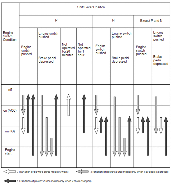
(a) This system has different power source mode patterns depending on the brake pedal condition and shift lever position.
|
Brake Pedal |
Shift Lever Position |
Power Source Mode Pattern |
|---|---|---|
|
Depressed |
P or N |
When the engine switch is pushed once.
|
|
Not depressed |
P |
Each time the engine switch is pushed.
|
|
Except P |
Each time the engine switch is pushed.
|
|
|
- |
P |
When the engine switch is on (IG) (engine running).
|
|
- |
Except P |
When the engine switch is on (IG) (engine running).
|
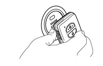
When the battery of the key is low or the signal communication is affected by wave noise, the push-button start function can be operated by holding the key against the engine switch.
- After approximately 1 hour has elapsed with the engine switch on (IG) and the shift lever in P, the power management control ECU will automatically cut the power supply (the power source mode will change to off).
- After approximately 20 minutes has elapsed with the engine switch on (ACC) and the shift lever in P, the power management control ECU will automatically cut the power supply (the power source mode will change to off).
- The illustration below shows the transition of power source modes.
Transition of power source mode:
HINT:
While the vehicle is being driven normally, operation of the engine switch is disabled. However, if the engine must be stopped in an emergency while the vehicle is being driven, pressing the engine switch for 2 seconds or more or pushing the engine switch 3 times or more in a row, stops the engine. Power source mode changes from start to on (ACC).
5. SYSTEM NOT OPERATING NORMALLY (DUE TO KEY BATTERY DEPLETION, ELECTRICAL NOISE, ETC.)
(a) To operate the push-button start function when the key battery is low or the signal communication is affected by wave noise, hold the key against the engine switch with the brake pedal depressed.
6. DIAGNOSIS
The power management control ECU can detect malfunctions in the push-button start function when the power source mode is on (IG).
When the ECU detects a malfunction, the amber indicator light of the engine switch flashes to warn the driver. At the same time, the ECU stores a 5-digit DTC (Diagnostic Trouble Code) in memory.
- The indicator light warning continues flashing for 15 seconds even after the power source mode is changed to off.
- The DTCs can be output by connecting the Techstream to the DLC3.
- The push-button start function cannot be operated if a malfunction occurs.
 Parts Location
PARTS LOCATION
ILLUSTRATION
ILLUSTRATION
...
 System Diagram
SYSTEM DIAGRAM
Communication Table
Transmitting ECU
(Transmitter)
Receiving ECU
(Receiver)
Signal
Line
ECM
Power manage ...
Other materials about Toyota 4Runner:
Open in Stop Light Switch Circuit (C1425)
DESCRIPTION
The skid control ECU receives the stop light switch assembly signal and detects
the brake pedal operation status.
The skid control ECU has an open detection circuit, which stores this DTC if
it detects an open in the stop light input line of ...
Reassembly
REASSEMBLY
CAUTION / NOTICE / HINT
HINT:
When installing the rear spoiler protector, heat the rear spoiler surface using
a heat light.
Standard:
Item
Temperature
Rear Spoiler
20 to 30°C (68 to 86°F)
...

0.0064