Toyota 4Runner: Airbag Signal Malfunction/Not Input (B15C4)
DESCRIPTION
If the DCM (Telematics Transceiver) detects an error in the communication between the DCM (Telematics Transceiver) and center airbag sensor assembly as a result of the DCM (Telematics Transceiver) self check, this DTC will be set.
|
DTC Code |
DTC Detection Condition |
Trouble Area |
|---|---|---|
|
B15C4 |
The DCM (Telematics Transceiver) detects an error in the signals from the center airbag sensor assembly when the ignition switch is ON. |
|
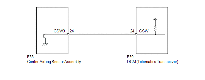
WIRING DIAGRAM
CAUTION / NOTICE / HINT
NOTICE:
components such as airbags. Before servicing (including removal or installation
of parts), be sure to read the Precaution in the SRS (See page
.gif) )
)
PROCEDURE
|
1. |
CHECK FOR DTC (AIRBAG SYSTEM) |
(a) Turn the ignition switch off.
(b) Connect the Techstream to the DLC3.
(c) Turn the ignition switch to ON and wait for 10 seconds.
(d) Check the DTC of "AIRBAG SYSTEM" (See page
).
|
Result |
Proceed to |
|---|---|
|
DTC B15C4 is not output |
A |
|
DTC B15C4 is output |
B |
| B | .gif) |
GO TO AIRBAG SYSTEM |
|
.gif)
|
2. |
CHECK DCM (TELEMATICS TRANSCEIVER) (GSW SIGNAL) |
|
(a) Remove the DCM (Telematics Transceiver) with the connectors connected
(See page |
|
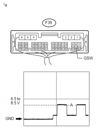
(b) Measure the voltage according to the value(s) in the table below.
Waveform|
Item |
Content |
|---|---|
|
Tester connection |
F39-24 (GSW) - Body ground |
|
Tool setting |
5.0 V/DIV., 20 ms/DIV. |
|
Vehicle condition |
Ignition switch ON |
|
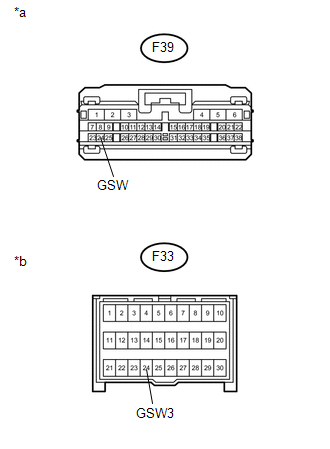
*a |
Component with harness connected (DCM [Telematics Transceiver]) |
|
Result |
Proceed to |
|---|---|
|
Higher than A |
A |
|
Below A |
B |
|
A |
C |
| B | |
GO TO STEP 4 |
| C | |
GO TO STEP 5 |
|
|
3. |
CHECK HARNESS AND CONNECTOR (FOR OPEN CIRCUIT) |
|
(a) Remove the center airbag sensor assembly with the connectors connected
(See page |
|
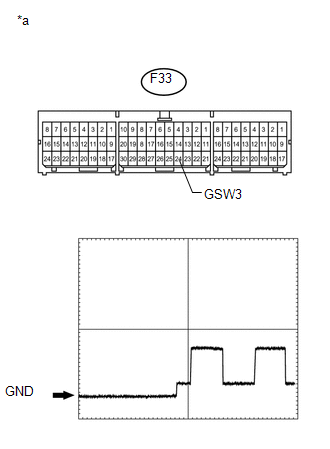
(b) Measure the voltage according to the value(s) in the table below.
Standard Voltage:
|
Tester Connection |
Switch Condition |
Specified Condition |
|---|---|---|
|
F33-24 (GSW3) - Body ground |
Ignition switch ON |
8.5 V or higher |
|
Item |
Content |
|---|---|
|
Tester connection |
F33-24 (GSW3) - Body ground |
|
Tool setting |
5.0 V/DIV., 20 ms/DIV. |
|
Vehicle condition |
Ignition switch ON |
|
*a |
Component with harness connected (Center Airbag Sensor Assembly) |
| OK | |
REPLACE CENTER AIRBAG SENSOR ASSEMBLY |
| NG | |
REPAIR OR REPLACE HARNESS OR CONNECTOR |
|
4. |
CHECK HARNESS AND CONNECTOR (FOR SHORT CIRCUIT) |
|
(a) Disconnect the F39 DCM (Telematics Transceiver) connector. |
|
(b) Measure the resistance according to the value(s) in the table below.
Standard Resistance:
|
Tester Connection |
Condition |
Specified Condition |
|---|---|---|
|
F39-24 (GSW) - Body ground |
Always |
10 kΩ or higher |
|
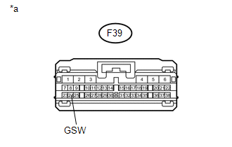
*a |
Front view of wire harness connector (to DCM [Telematics Transceiver]) |
| NG | |
GO TO STEP 6 |
|
|
5. |
REPLACE DCM (TELEMATICS TRANSCEIVER) |
(a) Replace the DCM (Telematics Transceiver) (See page
).
NOTICE:
- The ignition switch must be off.
- Do not replace the DCM (Telematics Transceiver) with one from another vehicle.
| NEXT | |
PERFORM DCM ACTIVATION |
|
6. |
CHECK HARNESS AND CONNECTOR (DCM - CENTER AIRBAG SENSOR ASSEMBLY) |
|
(a) Disconnect the F39 DCM (Telematics Transceiver) connector. |
|
(b) Disconnect the F33 center airbag sensor connector.
(c) Measure the resistance according to the value(s) in the table below.
Standard Resistance:
|
Tester Connection |
Condition |
Specified Condition |
|---|---|---|
|
F39-24 (GSW) - F33-24 (GSW3) |
Always |
Below 1 Ω |
|
F39-24 (GSW) - Body ground |
Always |
10 kΩ or higher |
|
*a |
Front view of wire harness connector (to DCM [Telematics Transceiver]) |
|
*b |
Front view of wire harness connector (to Center Airbag Sensor Assembly) |
| OK | |
REPLACE CENTER AIRBAG SENSOR ASSEMBLY |
| NG | |
REPAIR OR REPLACE HARNESS OR CONNECTOR |
 Short in GPS Antenna (B15C0,B15C1)
DESCRIPTION
This DTC is stored when the DCM (Telematics Transceiver) detects an open or a
short in the telephone and GPS antenna circuit. The DCM (Telematics Transceiver)
receives signals at a ra ...
 Manual (SOS) Switch Red Indicator Malfunction (B1570)
DESCRIPTION
This DTC is stored when the DCM (Telematics Transceiver) detects an open or short
in the manual (SOS) switch red indicator circuit of the manual (SOS) switch.
The manual (SOS) switch r ...
Other materials about Toyota 4Runner:
Seat heaters
1. On The indicator light comes on.
2. Adjusts the seat temperature The further you move the dial forward, the
warmer the seat becomes.
The seat heaters can be used when Vehicles without a smart key
system
The engine switch is in the “ON” positi ...
Problem Symptoms Table
PROBLEM SYMPTOMS TABLE
HINT:
Use the table below to help determine the cause of problem symptoms.
If multiple suspected areas are listed, the potential causes of the symptoms
are listed in order of probability in the "Suspected Area" ...

0.0076