Toyota 4Runner: System Diagram
SYSTEM DIAGRAM
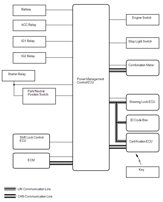 Communication Table
|
Transmitting ECU (Transmitter) |
Receiving ECU (Receiver) |
Signal |
Line |
|---|---|---|---|
|
ECM |
Power management control ECU |
Crankshaft position sensor signal |
CAN/Serial communication |
|
Combination meter |
Power management control ECU |
Vehicle speed signal |
CAN/Serial communication |
|
Steering lock ECU |
Power management control ECU |
Steering lock/unlock signal |
LIN/Serial communication |
|
Certification ECU |
Power management control ECU |
LIN master signal |
LIN |
|
Power management control ECU |
Certification ECU |
ID required signal |
LIN |
|
Key existence condition signal |
CAN |
 System Description
SYSTEM DESCRIPTION
1. PUSH-BUTTON START DESCRIPTION
(a) The push-button start function uses a push-type engine switch, which the
driver can operate by merely carrying the key. This system consists ...
 How To Proceed With Troubleshooting
CAUTION / NOTICE / HINT
HINT:
Use these procedures to troubleshoot the push-button start function.
*: Use the Techstream.
PROCEDURE
1.
VEHICLE BROUGHT T ...
Other materials about Toyota 4Runner:
Data List / Active Test
DATA LIST / ACTIVE TEST
1. DATA LIST
HINT:
Using the Techstream to read the Data List allows the values or states of switches,
sensors, actuators and other items to be read without removing any parts. This non-intrusive
inspection can be very useful bec ...
Power Seat Position is not Memorized
DESCRIPTION
When the seat memory SET switch and a memory switch (M1 or M2) are pressed simultaneously,
the main body ECU commands the position control ECU through CAN communication to
record the value of each position sensor.
WIRING DIAGRAM
CAUTION / ...

0.009