Toyota 4Runner: System Diagram
SYSTEM DIAGRAM
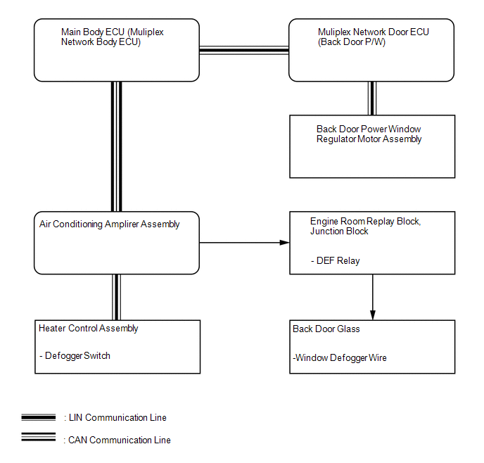 Communication Table
|
Transmitter |
Receiver |
Signal |
Line |
|---|---|---|---|
|
Heater control assembly |
Air conditioning amplifier assembly |
Defogger switch signal |
LIN |
|
Multiplex network door ECU (Back door P/W) |
Main body ECU (Multiplex network body ECU) |
Back door window position signal |
LIN |
|
Back door power window regulator motor |
Multiplex network door ECU (Back door P/W) |
Back door window position signal |
LIN |
|
Main body ECU (Multiplex network body ECU) |
Air conditioning amplifier assembly |
Back door window position signal |
CAN |
 System Description
SYSTEM DESCRIPTION
1. WINDOW DEFOGGER SYSTEM DESCRIPTION
The thin heater wires of the defogger system are attached to the rear window
and defog the rear window surface quickly. The system only ope ...
 How To Proceed With Troubleshooting
CAUTION / NOTICE / HINT
HINT:
Inspect the window defogger system after confirming that the back door
power window system of the power window control system is operating normally.
...
Other materials about Toyota 4Runner:
Adjustment
ADJUSTMENT
PROCEDURE
1. CHECK BRAKE PEDAL HEIGHT
(a) Check the brake pedal height.
Pedal height from Floor panel:
158.8 to 168.8 mm (6.25 to 6.46 in.)
Text in Illustration
*1
Rod Operating Adapter
...
Cleaning and protecting the vehicle interior
The following procedures will help protect your vehicle’s interior and
keep it in top condition:
Protecting the vehicle interior
Remove dirt and dust using a vacuum cleaner. Wipe dirty surfaces with a cloth
dampened with lukewarm water.
Cleaning the ...

0.0269