Toyota 4Runner: System Diagram
SYSTEM DIAGRAM
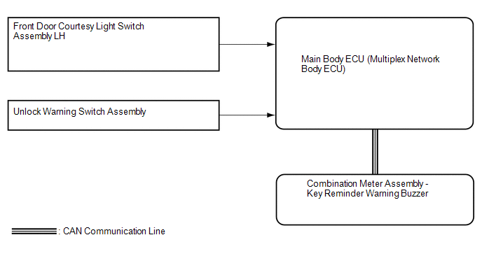 Communication Table
|
Sender |
Receiver |
Signal |
Line |
|---|---|---|---|
|
Main body ECU (Multiplex network body ECU) |
Combination meter assembly |
Front door courtesy light switch LH signal |
CAN |
|
Main body ECU (Multiplex network body ECU) |
Combination meter assembly |
Unlock warning switch signal |
CAN |
 Parts Location
PARTS LOCATION
ILLUSTRATION
...
 How To Proceed With Troubleshooting
CAUTION / NOTICE / HINT
HINT:
Use the following procedures to troubleshoot the key reminder warning
system.
*: Use the Techstream.
PROCEDURE
1.
VEHICLE ...
Other materials about Toyota 4Runner:
System Description
SYSTEM DESCRIPTION
1. WIRELESS DOOR LOCK CONTROL SYSTEM DESCRIPTION
(a) This system locks/unlocks the vehicle doors remotely. The wireless control
system has the following features:
The door control receiver performs the code identification procedu ...
How To Proceed With Troubleshooting
CAUTION / NOTICE / HINT
HINT:
Use these procedures to troubleshoot the sliding roof system.
*: Use the Techstream.
PROCEDURE
1.
VEHICLE BROUGHT TO WORKSHOP
NEXT
...

0.0068