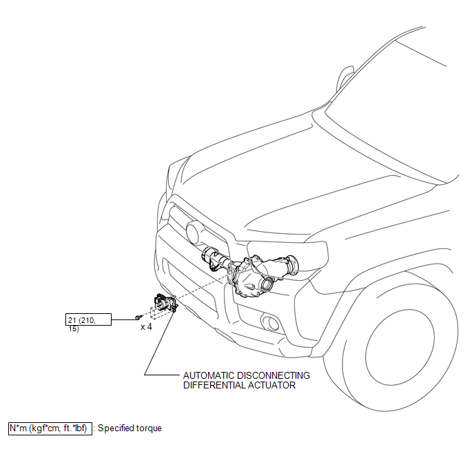
Toyota 4Runner: Automatic Disconnecting Differential Actuator
Components
COMPONENTS
ILLUSTRATION
Installation
INSTALLATION
PROCEDURE
1. INSTALL AUTOMATIC DISCONNECTING DIFFERENTIAL ACTUATOR
(a) Remove any old FIPG material.
NOTICE:
Be careful not to drop oil on the contact surfaces of the actuator and clutch case.
(b) Using gasoline or alcohol, wipe off any residual FIPG material on the contact surfaces.
|
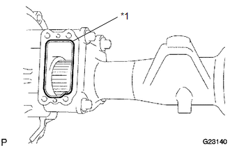
(c) Apply seal packing to the differential tube as shown in the illustration. Seal packing: Toyota Genuine Seal Packing 1281, Three Bond 1281 or equivalent Text in Illustration
HINT: Install the actuator within 10 minutes of applying seal packing. |
|
(d) Clean the threads of the 4 bolts and retainer bolt holes with toluene or trichloroethylene.
(e) Apply adhesive to 2 or 3 threads at the tip of the bolts.
Adhesive:
Toyota Genuine Adhesive 1324, Three Bond 1324 or equivalent
(f) Install the actuator to the differential tube with the 4 bolts.
Torque:
21 N·m {210 kgf·cm, 15 ft·lbf}
(g) Connect the actuator hose and connector.
(h) Support the differential with a jack.
(i) Install the 2 front mounting bolts and 2 nuts.
Torque:
137 N·m {1400 kgf·cm, 101 ft·lbf}
(j) Install the No. 1 differential mounting nut.
Torque:
87 N·m {887 kgf·cm, 64 ft·lbf}
(k) Install the differential breather tube bracket with the bolt.
Torque:
13 N·m {133 kgf·cm, 10 ft·lbf}
2. ADD DIFFERENTIAL OIL
(a) Add differential oil (See page .gif) ).
).
3. CHECK FOR DIFFERENTIAL OIL LEAKAGE
4. INSTALL REAR ENGINE UNDER COVER ASSEMBLY
5. INSTALL NO. 1 ENGINE UNDER COVER
6. INSTALL FRONT SIDE MEMBER TO FRONT SUSPENSION CROSSMEMBER BRACE
Removal
REMOVAL
PROCEDURE
1. REMOVE FRONT SIDE MEMBER TO FRONT SUSPENSION CROSSMEMBER BRACE
2. REMOVE NO. 1 ENGINE UNDER COVER
.gif)
3. REMOVE REAR ENGINE UNDER COVER ASSEMBLY
4. DRAIN DIFFERENTIAL OIL
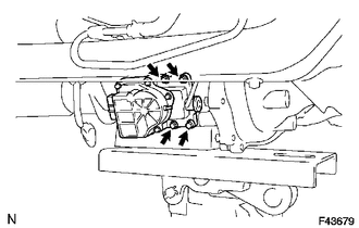
5. REMOVE AUTOMATIC DISCONNECTING DIFFERENTIAL ACTUATOR
|
(a) Remove the bolt and disconnect the differential breather tube bracket. |
|
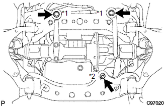
(b) Support the differential with a jack.
(c) Remove No. 1 differential mounting nut.
(d) Remove the 2 mounting bolts and nut.
Text in Illustration|
*1 |
Mounting Bolt |
|
*2 |
Mounting Nut |
(e) Disconnect the actuator hose and connector.
(f) Lower the jack.
|
(g) Remove the 4 bolts and actuator. |
|

 Axle System
...
Other materials about Toyota 4Runner:
System Diagram
SYSTEM DIAGRAM
Communication Table
Sender
Receiver
Signal
Line
ECM
Main Body ECU (Multiplex Network Body ECU)
Shift position P signal
Transmission informatio ...
Green And Red Indicators Blink Simultaneously
DESCRIPTION
After the ignition switch is turned to ON, the DCM (Telematics Transceiver) will
enter a self check mode. The manual (SOS) switch red indicator will illuminate for
2 seconds and turn off followed by the manual (SOS) switch green indicator illu ...

0.008