
Toyota 4Runner: System Diagram
Toyota 4Runner Service Manual / Vehicle Interior / Lighting (int) / Lighting System / System Diagram
SYSTEM DIAGRAM
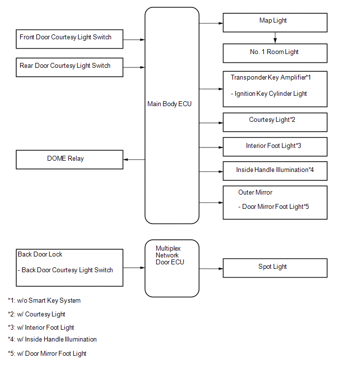
 System Description
SYSTEM DESCRIPTION
1. ILLUMINATION CONTROL SYSTEM (Illuminated Entry System)
(a) The illuminated entry system has the following control functions:
Control
Outline
L ...
 Customize Parameters
CUSTOMIZE PARAMETERS
1. CUSTOMIZING FUNCTION WITH TECHSTREAM
HINT:
The following items can be customized.
NOTICE:
When the customer requests a change in a function, first make sure that
...
Other materials about Toyota 4Runner:
Disassembly
DISASSEMBLY
PROCEDURE
1. REMOVE RADIATOR GRILLE
2. REMOVE NO. 2 ENGINE ROOM WIRE
(a) Disconnect each connector.
(b) Detach the 9 clamps to remove the No. 2 engine room wire.
3. REMOVE NO. 1 ULTRASONIC SENSOR
4. REMOVE ULTRASONIC SENSOR CLIP
...
Generator Signal Circuit
DESCRIPTION
When the engine is started, the generator assembly turns on and a voltage pulse
signal is generated.
This signal is used by the air conditioning amplifier assembly.
The signal expressing the amount of output from the generator assembly is one ...
© 2016-2026 | www.to4runner.net

0.0082
0.0082