Toyota 4Runner: System Diagram
Toyota 4Runner Service Manual / Vehicle Interior / Seat / Front Power Seat Control System(w/o Memory) / System Diagram
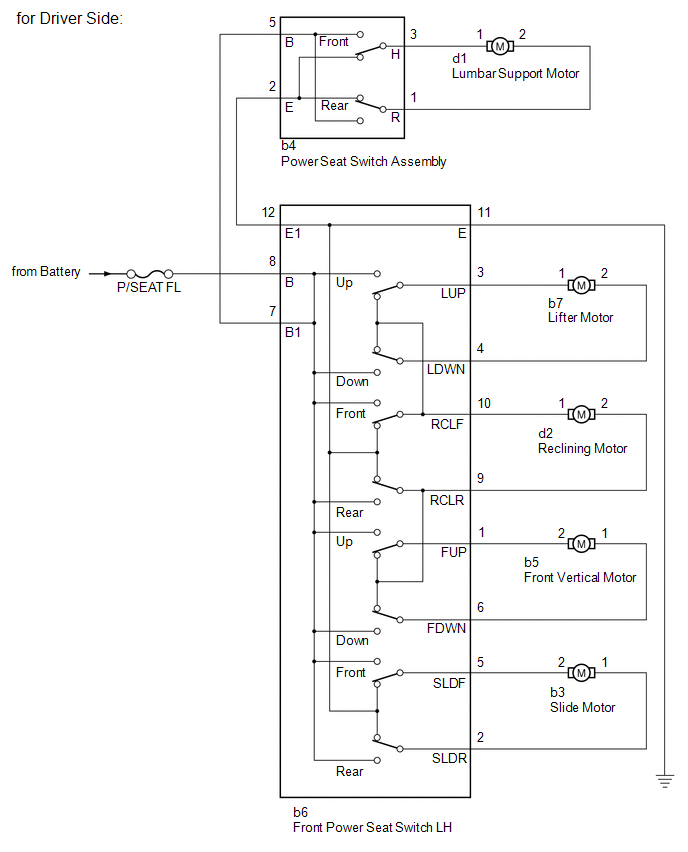
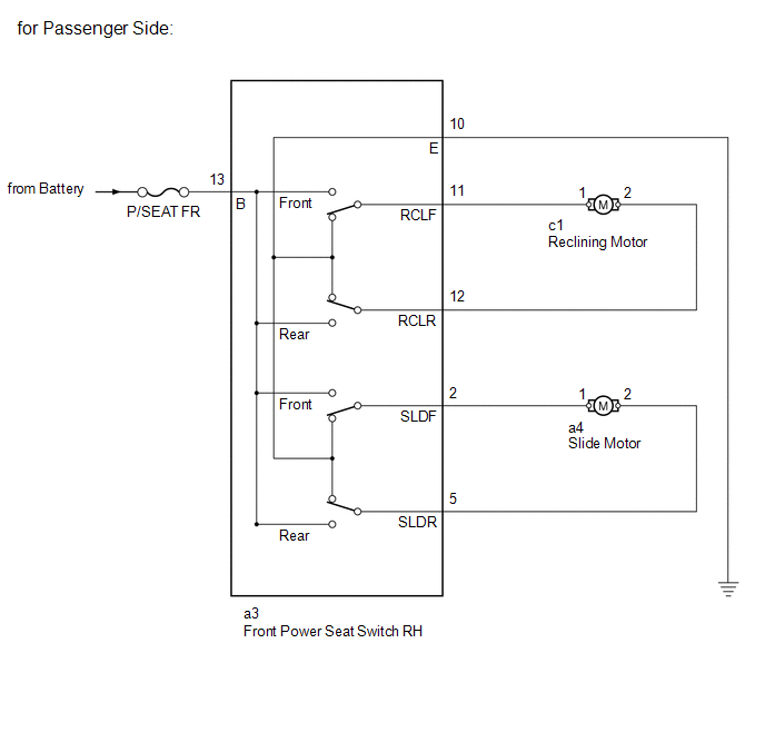
SYSTEM DIAGRAM
 Precaution
PRECAUTION
1. IGNITION SWITCH EXPRESSIONS
(a) The type of ignition switch used on this model differs depending on the specifications
of the vehicle. The expressions listed in the table below are u ...
 Operation Check
OPERATION CHECK
1. CHECK FRONT POWER SEAT FUNCTION
(a) Check the basic functions.
Text in Illustration
*a
Sliding function
*b
Front vertical func ...
Other materials about Toyota 4Runner:
No Communication in Immobiliser System (B2796,B2798)
DESCRIPTION
DTC B2796 is stored when a key is inserted into the ignition key cylinder
but no communication occurs between the key and transponder key ECU assembly.
DTC B2798 is stored when a key is inserted into the ignition key cylinder
...
Reassembly
REASSEMBLY
CAUTION / NOTICE / HINT
HINT:
When installing the rear spoiler protector, heat the rear spoiler surface using
a heat light.
Standard:
Item
Temperature
Rear Spoiler
20 to 30°C (68 to 86°F)
...
© 2016-2026 | www.to4runner.net

0.0275
0.0275