
Toyota 4Runner: Tachometer Malfunction
DESCRIPTION
In this circuit, the meter CPU receives engine speed signals from the ECM using the CAN communication system. The meter CPU displays the engine speed, which is calculated based on the data received from the ECM.
WIRING DIAGRAM
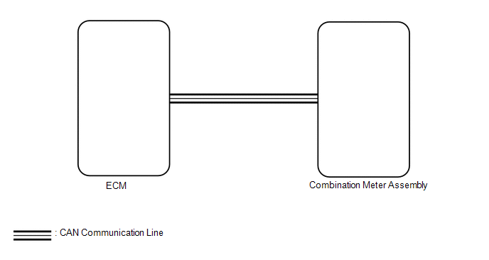
PROCEDURE
|
1. |
CHECK CAN COMMUNICATION SYSTEM |
(a) Check if a CAN communication DTC is output (See page
.gif) ).
).
Result
|
Result |
Proceed to |
|---|---|
|
CAN communication DTC is not output |
A |
|
CAN communication DTC is output |
B |
| B | .gif) |
GO TO CAN COMMUNICATION SYSTEM |
|
.gif)
|
2. |
PERFORM ACTIVE TEST USING TECHSTREAM (TACHO METER OPERATION) |
(a) Use the Active Test to check the operation of the tachometer (See page
).
Combination Meter
|
Tester Display |
Test Part |
Control Range |
Diagnostic Note |
|---|---|---|---|
|
Tacho Meter Operation |
Tachometer |
0, 1000, 2000, 3000, 4000, 5000, 6000, 7000 (rpm) |
Confirm that the vehicle is stopped with the engine idling. |
OK:
Tachometer indication is normal.
| NG | |
REPLACE COMBINATION METER ASSEMBLY |
|
|
3. |
READ VALUE USING TECHSTREAM (ENGINE RPM) |
(a) Use the Data List to check the engine speed (See page
).
Combination Meter
|
Tester Display |
Measurement Item/Range |
Normal Condition |
Diagnostic Note |
|---|---|---|---|
|
Engine Rpm |
Engine speed/Min.: 0 rpm, Max.: 12800 rpm |
600 to 700 rpm (When idling) |
If the data received from the ECM exceeds the range that can be displayed on the meter, the meter continues to display the maximum value. |
OK:
Engine speed displayed on the Techstream is almost the same as the tachometer indication.
(b) Record the engine speed displayed on the Techstream.
HINT:
Check the engine speed when the engine is fully warmed up, and the air conditioning and all electrical accessories are off.
| NG | |
REPLACE COMBINATION METER ASSEMBLY |
|
|
4. |
READ VALUE USING TECHSTREAM (ENGINE SPEED) |
(a) Use the Data List to check the engine speed (See page
).
Engine and ECT
|
Tester Display |
Measurement Item/Range |
Normal Condition |
Diagnostic Note |
|---|---|---|---|
|
Engine Speed |
Engine speed/Min.: 0 rpm, Max.: 16383 rpm |
600 to 700 rpm (When idling) |
- |
OK:
Engine speed displayed on the Techstream is almost the same as the previously recorded Techstream value (Body Electrical / Combination Meter / Data List / Engine Rpm).
| NG | |
GO TO SFI SYSTEM |
|
|
5. |
REPLACE ECM |
(a) Replace the ECM with a new or normally functioning one (See page
).
OK:
The operation of the tachometer returns to normal.
| OK | |
END |
| NG | |
REPLACE COMBINATION METER ASSEMBLY |
 Fuel Receiver Gauge Malfunction
DESCRIPTION
The fuel sender gauge has a variable resistance mechanism. The resistance
decreases when the fuel amount increases, and the resistance increases when
the fuel amount decrea ...
 Engine Coolant Temperature Receiver Gauge Malfunction
DESCRIPTION
In this circuit, the meter CPU receives engine coolant temperature signals from
the ECM using the CAN communication system. The meter CPU displays the engine coolant
temperature, whic ...
Other materials about Toyota 4Runner:
Abbreviations Used In Manual
ABBREVIATIONS USED IN MANUAL
Abbreviation
Meaning
ABS
Anti-Lock Brake System
A/C
Air Conditioner
AC
Alternating Current
ACC
A ...
Hands-free phone system (for cellular phone) features
This system supports Bluetooth®, which allows you to make or receive calls
without using cables to connect a cellular phone and the system, and without
operating the cellular phone.
Owners of models equipped with a Display Audio system should refer to th ...

0.0073