Toyota 4Runner: Terminals Of Ecu
TERMINALS OF ECU
1. CHECK AIR CONDITIONING AMPLIFIER ASSEMBLY
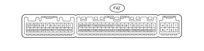
(a) Disconnect the F42 air conditioning amplifier connector.
(b) Measure the voltage and resistance according to the value(s) in the table below.
|
Terminal No. (Symbol) |
Wiring Color |
Terminal Description |
Condition |
Specified Condition |
|---|---|---|---|---|
|
F42-21 (B) - F42-14 (GND) |
V - W-B |
Battery power source |
Always |
11 to 14 V |
|
F42-1 (IG+) - F42-14 (GND) |
L - W-B |
Ignition switch power supply |
Ignition switch ON |
11 to 14 V |
|
F42-1 (IG+) - F42-14 (GND) |
L - W-B |
Ignition switch power supply |
Ignition switch off |
Below 1 V |
|
F42-14 (GND) - Body ground |
W-B - Body ground |
Ground |
Always |
Below 1 Ω |
- If the result is not as specified, there may be a malfunction on the wire harness side.
(c) Reconnect the F42 air conditioning amplifier connector.
(d) Measure the voltage according to the value(s) in the table below.
|
Terminal No. (Symbol) |
Wiring Color |
Terminal Description |
Condition |
Specified Condition |
|---|---|---|---|---|
|
F42-38 (RDEF) - F42-14 (GND) |
P - W-B |
Rear defogger signal |
Ignition switch ON, rear window defogger switch off |
11 to 14 V |
|
F42-38 (RDEF) - F42-14 (GND) |
P - W-B |
Rear defogger signal |
Ignition switch ON, rear window defogger switch on |
Below 1 V |
- If the result is not as specified, there may be a malfunction in the air conditioning amplifier.
2. CHECK HEATER CONTROL ASSEMBLY

(a) Disconnect the F29 heater control connector.
(b) Measure the resistance and voltage according to the value(s) in the table below.
|
Terminal No. (Symbol) |
Wiring Color |
Terminal Description |
Condition |
Specified Condition |
|---|---|---|---|---|
|
F29-4 (IG+) - F29-11 (GND) |
L - W-B |
Ignition switch power supply |
Ignition switch ON |
11 to 14 V |
|
F29-4 (IG+) - F29-11 (GND) |
L - W-B |
Ignition switch power supply |
Ignition switch off |
Below 1 V |
|
F29-11 (GND) - Body ground |
W-B - Body ground |
Ground |
Always |
Below 1 Ω |
If the result is not as specified, there may be a malfunction on the wire harness side.
 Problem Symptoms Table
PROBLEM SYMPTOMS TABLE
HINT:
Use the table below to help determine the cause of problem symptoms.
If multiple suspected areas are listed, the potential causes of the symptoms
are lis ...
 Data List / Active Test
DATA LIST / ACTIVE TEST
1. ACTIVE TEST
HINT:
Using the Techstream to perform Active Tests allows relays, VSVs, actuators and
other items to be operated without removing any parts. This non-intrus ...
Other materials about Toyota 4Runner:
Adjustment
ADJUSTMENT
CAUTION / NOTICE / HINT
HINT:
Use the same procedure for the RH side and LH side.
The following procedure is for the LH side.
Centering bolts are used to mount the door hinge to the vehicle body
and door. The door cannot b ...
Removal
REMOVAL
PROCEDURE
1. DISCONNECT CABLE FROM NEGATIVE BATTERY TERMINAL
CAUTION:
Wait at least 90 seconds after disconnecting the cable from the negative (-)
battery terminal to disable the SRS system.
NOTICE:
When disconnecting the cable, some systems ne ...

0.0149