Toyota 4Runner: Terminals Of Ecu
TERMINALS OF ECU
1. CHECK DRIVER SIDE JUNCTION BLOCK ASSEMBLY, MAIN BODY ECU (MULTIPLEX NETWORK BODY ECU)
.png)
(a) Remove the main body ECU (See page .gif) ).
).
(b) Measure the voltage and resistance according to the value(s) in the table below.
|
Terminal No. (Symbol) |
Wiring Color |
Terminal Description |
Condition |
Specified Condition |
|---|---|---|---|---|
|
A-29 (ACC) - Body ground |
- |
ACC power supply |
Ignition switch ACC |
11 to 14 V |
|
A-30 (BECU) - Body ground |
- |
Battery power supply |
Always |
11 to 14 V |
|
A-32 (IG) - Body ground |
- |
Ignition power supply |
Ignition switch ON |
11 to 14 V |
|
A-11 (GND1) - Body ground |
- |
Ground |
Always |
Below 1 Ω |
|
F10-3 (GND2) - Body ground |
W-B - Body ground |
Ground |
Always |
Below 1 Ω |
If the result is not as specified, there may be a malfunction on the wire harness side.
(c) Install the main body ECU (See page ).
(d) Measure the voltage according to the value(s) in the table below.
|
Terminal No. (Symbol) |
Wiring Color |
Terminal Description |
Condition |
Specified Condition |
|---|---|---|---|---|
|
F8-3 (LCTY) - 2B-4 (GND1) |
V - W-B |
Rear door courtesy light switch LH signal |
Rear door LH open |
Below 1 V |
|
Rear door LH closed |
11 to 14 V |
|||
|
F9-2 (DOMR) - 2B-4 (GND1) |
V - W-B |
DOME relay drive output |
Battery saving control not operating |
11 to 14 V |
|
Battery saving control operating |
Below 1 V |
|||
|
F10-27 (RCTY) - 2B-4 (GND1) |
R - W-B |
Rear door courtesy light switch RH signal |
Rear door RH open |
Below 1 V |
|
Rear door RH closed |
11 to 14 V |
|||
|
F10-4 (MILE) - 2B-4 (GND1)*1 |
W - W-B |
Door mirror foot light signal output |
Door mirror foot light on |
11 to 14 V |
|
Door mirror foot light off |
Below 1 V |
|||
|
2B-18 (ILE) - 2B-4 (GND1) |
G - W-B |
Interior light signal |
Interior light on |
Below 1 V |
|
Interior light off |
11 to 14 V |
|||
|
2B-15 (FRCY) - 2B-4 (GND1) |
B - W-B |
Front door courtesy light switch RH signal |
Front door RH open |
Below 1 V |
|
Front door RH closed |
11 to 14 V |
|||
|
2B-36 (FSPT) - 2B-4 (GND1)*2, *3 |
SB - W-B |
Front door inside handle illumination, rear door inside handle illumination RH and interior foot light signal |
Front door inside handle illumination and interior foot light on |
Below 1 V |
|
Front door inside handle illumination and interior foot light off |
11 to 14 V |
|||
|
2F-27 (FLCY) - 2B-4 (GND1) |
R - W-B |
Front door courtesy light switch LH signal |
Front door LH open |
Below 1 V |
|
Front door LH closed |
11 to 14 V |
|||
|
2F-36 (FSPT) - 2B-4 (GND1)*2 |
SB - W-B |
Rear door inside handle illumination LH signal |
Rear door inside handle illumination on |
Below 1 V |
|
Rear door inside handle illumination off |
11 to 14 V |
- *1: w/ Door Mirror Foot Light
- *2: w/ Inside Handle Illumination
- *3: w/ Interior Foot Light
If the result is not as specified, the main body ECU may have a malfunction.
2. CHECK MULTIPLEX NETWORK DOOR ECU
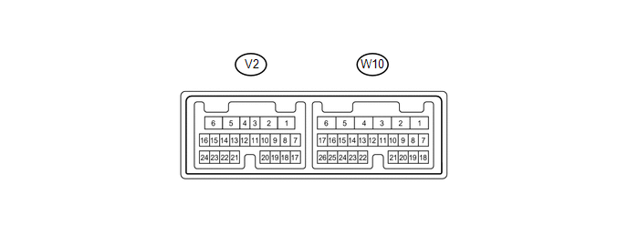
(a) Disconnect the V2 and W10 multiplex network door ECU connectors.
(b) Measure the voltage and resistance according to the value(s) in the table below.
|
Terminal No. (Symbol) |
Wiring Color |
Terminal Description |
Condition |
Specified Condition |
|---|---|---|---|---|
|
V2-17 (B1) - Body ground |
R - Body ground |
Battery power supply |
Always |
11 to 14 V |
|
V2-6 (GND) - Body ground |
W-B - Body ground |
Ground |
Always |
Below 1 Ω |
If the result is not as specified, there may be a malfunction on the wire harness side.
(c) Reconnect the V2 and W10 multiplex network door ECU connectors.
(d) Measure the voltage according to the value(s) in the table below.
|
Terminal No. (Symbol) |
Wiring Color |
Terminal Description |
Condition |
Specified Condition |
|---|---|---|---|---|
|
W10-10 (BDCY) - W10-18 (CTYE) |
P - G |
Back door courtesy light switch signal |
Back door open |
Below 1 V |
|
Back door closed |
Pulse generation (See waveform 1 or 2) |
|||
|
W10-22 (LGLP) - V2-6 (GND) |
L - W-B |
Spot light LH signal |
Spot light LH on |
Pulse generation (See waveform 3) |
|
Spot light LH off |
Pulse generation (See waveform 4) |
|||
|
W10-23 (LGP2) - V2-6 (GND) |
L - W-B |
Spot light RH signal |
Spot light RH on |
Pulse generation (See waveform 3) |
|
Spot light RH off |
Pulse generation (See waveform 4) |
|||
|
W10-25 (B2) - V2-6 (GND) |
R - W-B |
Battery power supply |
Always |
11 to 14 V |
|
W10-26 (B3) - V2-6 (GND) |
R - W-B |
Battery power supply |
Always |
11 to 14 V |
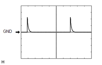
(1) Waveform 1
|
Item |
Content |
|---|---|
|
Terminal No. (Symbol) |
W10-10 (BDCY) - W10-18 (CTYE) |
|
Tool setting |
5 V/DIV., 10 ms/DIV. |
|
Condition |
Back door closed |
(2) Waveform 2
.png)
|
Item |
Content |
|---|---|
|
Terminal No. (Symbol) |
W10-10 (BDCY) - W10-18 (CTYE) |
|
Tool setting |
5 V/DIV., 10 ms/DIV. |
|
Condition |
Back door closed |
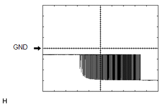
(3) Waveform 3
|
Item |
Content |
|---|---|
|
Terminal No. (Symbol) |
W10-22 (LGLP) - V2-6 (GND) W10-23 (LGP2) - V2-6 (GND) |
|
Tool setting |
5 V/DIV., 200 ms/DIV. |
|
Condition |
|
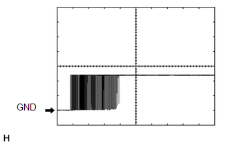
(4) Waveform 4
|
Item |
Content |
|---|---|
|
Terminal No. (Symbol) |
W10-22 (LGLP) - V2-6 (GND) W10-23 (LGP2) - V2-6 (GND) |
|
Tool setting |
5 V/DIV., 200 ms/DIV. |
|
Condition |
|
 Problem Symptoms Table
PROBLEM SYMPTOMS TABLE
HINT:
Use the table below to help determine the cause of problem symptoms. If multiple
suspected areas are listed, the potential causes of the symptoms are listed in order
...
 Data List / Active Test
DATA LIST / ACTIVE TEST
1. DATA LIST
HINT:
Using the Techstream to read the Data List allows the values or states of switches,
sensors, actuators and other items to be read without removing any p ...
Other materials about Toyota 4Runner:
Dtc Check / Clear
DTC CHECK / CLEAR
1. CHECK DTC
(a) Connect the Techstream to the DLC3.
(b) Turn the engine switch on (IG).
(c) Turn the Techstream on.
(d) Enter the following menus: Body Electrical / (desired system) / Trouble Codes.
(e) Check for DTCs.
HINT:
Refer to ...
Installation
INSTALLATION
CAUTION / NOTICE / HINT
HINT:
A bolt without a torque specification is shown in the standard bolt chart (See
page ).
PROCEDURE
1. INSTALL PINTLE HOOK SUPPORT TUBE SUB-ASSEMBLY (w/ Pintle Hook)
(a) Install the pintle hook support tube sub- ...

0.0093