Toyota 4Runner: Terminals Of Ecu
TERMINALS OF ECU
1. COMBINATION METER ASSEMBLY

(a) Measure the voltage and resistance according to the value(s) in the table below.
|
Terminal No. (Symbol) |
Wiring Color |
Terminal Description |
Condition |
Specified Condition |
|---|---|---|---|---|
|
1 (CANH) - Body ground |
L - Body ground |
CAN communication signal |
Ignition switch off |
200 Ω or higher |
|
2 (CANL) - Body ground |
W - Body ground |
CAN communication signal |
Ignition switch off |
200 Ω or higher |
|
3 (MSSL) - Body ground |
P - Body ground |
Steering pad switch assembly (DISP switch) signal |
Ignition switch to ON, DISP switch not pressed |
4 to 5 V |
|
Ignition switch to ON, DISP switch pressed |
Below 1 V |
|||
|
6 (LINT) - Body ground*1 |
LG - Body ground |
LIN (Drive monitor switch communication) |
Ignition switch ON |
Pulse generation |
|
7 (RR) - Body ground*2 |
Y - Body ground |
No. 1 Ultrasonic sensor (for rear corner RH) |
Clearance warning indication for rear corner RH is displayed |
Below 3 V |
|
8 (S) - Body ground |
V - Body ground |
Oil pressure switch signal |
Ignition switch ON, oil pressure warning light off |
11 to 14 V |
|
Ignition switch ON, oil pressure warning light on |
Below 1 V |
|||
|
9 (TIRE) - Body ground |
G - Body ground |
Tire pressure warning light signal |
Ignition switch ON, tire pressure warning light off |
11 to 14 V |
|
Ignition switch ON, tire pressure warning light blinking |
Below 1 V |
|||
|
10 (IL2-) - Body ground |
GR - Body ground |
Illumination signal |
Light control switch off |
Below 1 V |
|
Light control switch in tail or head position |
Pulse generation |
|||
|
11 (ILL-) - Body ground |
GR - Body ground |
Illumination signal |
Light control switch off |
Below 1 V |
|
Light control switch in tail or head position |
Pulse generation |
|||
|
12 (RL) - Body ground*2 |
GR - Body ground |
No. 1 Ultrasonic sensor (for rear corner LH) |
Clearance warning indication for rear corner LH is displayed |
Below 3 V |
|
13 (MGND) - Body ground |
W-B - Body ground |
Ground (Signal ground) |
Always |
Below 1 V |
|
14 (SW) - Body ground*7 |
V - Body ground |
Brake fluid level warning switch signal |
Ignition switch ON, brake fluid level warning light on |
Below 1 V |
|
Ignition switch ON, brake fluid level warning light off |
11 to 14 V |
|||
|
15 (B) - Body ground |
L - Body ground |
Battery |
Always |
11 to 14 V |
|
17 (IG+) - Body ground |
R - Body ground |
Ignition switch signal |
Ignition switch off |
Below 1 V |
|
Ignition switch ON |
11 to 14 V |
|||
|
18 (BK) - Body ground*2 |
SB - Body ground |
No. 1 Ultrasonic sensor (for rear corner LH and RH) |
Clearance warning indication for back right and left sensor are displayed |
Below 3 V |
|
19 (E3) - Body ground |
B - Body ground |
Ground (Fuel ground) |
Always |
Below 1 V |
|
20 (E1) - Body ground |
W-B - Body ground |
Ground |
Always |
Below 1 V |
|
21 (STP+) - Body ground*3 |
G - Body ground |
Automatic Running Boards warning light signal |
Automatic Running Boards warning light on or blinking |
11 to 14 V |
|
Automatic Running Boards warning light off |
Below 1 V |
|||
|
22 (STPA) - Body ground*3 |
W - Body ground |
Ground |
Automatic Running Boards warning light off |
11 to 14 V |
|
Ignition switch ON, automatic running boards warning light on |
Below 1 V |
|||
|
23 (MSCH) - Body ground*4 |
LG - Body ground |
CAN communication signal |
Ignition switch off |
200 Ω or higher |
|
24 (MSCL) - Body ground*4 |
W - Body ground |
CAN communication signal |
Ignition switch off |
200 Ω or higher |
|
25 (B) - Body ground |
SB - Body ground |
Turn indicator light signal |
Ignition switch ON, turn RH indicator light off |
Below 1 V |
|
Ignition switch ON, turn RH indicator light blinking |
11 to 14 V |
|||
|
26 (CHG-) - Body ground |
P - Body ground |
Charge warning light signal |
Ignition switch ON, charge warning light off |
11 to 14 V |
|
Ignition switch ON, charge warning light on |
Below 1 V |
|||
|
27 (WLVL) - Body ground*5 |
R - Body ground |
Washer level warning switch signal |
Ignition switch ON, washer level warning light off |
11 to 14 V |
|
Ignition switch ON, washer level warning light on |
Below 1 V |
|||
|
28 (+S) - Body ground |
SB - Body ground |
Speed signal for other systems (Output) |
Driving at approx. 20 km/h (12 mph) |
Pulse generation (See waveform 1) |
|
29 (SI) - Body ground |
G - Body ground |
Speed signal for other systems (Input) |
Driving at approx. 20 km/h (12 mph) |
Pulse generation (See waveform 1) |
|
30 (CHK) - Body ground |
L - Body ground |
MIL (Check engine warning light) signal |
Ignition switch ON, MIL (Check engine warning light) off |
11 to 14 V |
|
Ignition switch ON, MIL (Check engine warning light) on |
Below 1 V |
|||
|
31 (OP) - Body ground*2 |
LG - Body ground |
Clearance warning ECU signal |
Clearance warning indication is displayed |
Below 3 V |
|
32 (FL) - Body ground*2 |
P - Body ground |
No. 1 Ultrasonic sensor (for front corner LH) |
Clearance warning indication for front corner LH is displayed |
Below 3 V |
|
33 (B) - Body ground |
Y - Body ground |
Turn indicator light signal |
Ignition switch ON, turn LH indicator light off |
Below 1 V |
|
Ignition switch ON, turn LH indicator light blinking |
11 to 14 V |
|||
|
35 (FR) - Body ground*2 |
B - Body ground |
No. 1 Ultrasonic sensor (for front corner RH) |
Clearance warning indication for front corner RH is displayed |
Below 3 V |
|
36 (TC) - Body ground*6 |
W - Body ground |
TAIL cancel switch signal |
TAIL cancel switch off |
1 MΩ or higher |
|
TAIL cancel switch on |
Below 1 Ω |
|||
|
37 (RHIG) - Body ground*6 |
B - Body ground |
Power source for light control rheostat |
Ignition switch ON |
4.6 to 5.4 V |
|
38 (TR) - Body ground*6 |
GR - Body ground |
Light control rheostat signal |
Light control rheostat dial fully turned downward |
Below 1 Ω |
|
Light control rheostat dial fully turned upward |
8 to 12 kΩ |
|||
|
39 (E2) - Body ground*6 |
LG - Body ground |
Light control rheostat switch ground |
Always |
Below 1 Ω |
|
40 (L) - Body ground |
W - Body ground |
Fuel level signal |
Ignition switch ON, fuel level warning light off |
Below 4 V |
|
Ignition switch ON, fuel level warning light on |
4 to 9 V |
- *1: w/ CRAWL Control
- *2: w/ Intuitive Parking Assist System
- *3: w/ Automatic Running Board System
- *4: w/ Seat Position Memory
- *5: w/ Level Warning Switch Assembly
- *6: w/ Light Control Rheostat
- *7: for 2WD
(b) Using an oscilloscope, check waveform 1.
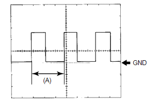 Waveform 1 (Reference)
|
Item |
Condition |
|---|---|
|
Tool setting |
5 V/DIV., 20 ms./DIV. |
|
Vehicle condition |
Driving at approx. 20 km/h (12 mph) |
HINT:
When the system is functioning normally, one wheel revolution generates 4 pulses. As the vehicle speed increases, the width indicated by (A) in the illustration narrows.
2. ACCESSORY METER ASSEMBLY
.png)
(a) Measure the voltage and resistance according to the value(s) in the table below.
|
Terminal No. (Symbol) |
Wiring Color |
Terminal Description |
Condition |
Specified Condition |
|---|---|---|---|---|
|
G36-1 (B) - Body ground |
L - Body ground |
Battery |
Always |
11 to 14 V |
|
G36-2 (ACC) - Body ground |
P - Body ground |
Ignition switch signal |
Ignition switch off |
Below 1 V |
|
Ignition switch ACC |
11 to 14 V |
|||
|
G36-3 (ILL+) - Body ground |
G - Body ground |
Illumination signal |
Light control switch in tail or head position |
11 to 14 V |
|
G36-7 (E) - Body ground |
W-B - Body ground |
Ground |
Always |
Below 1 Ω |
 Problem Symptoms Table
PROBLEM SYMPTOMS TABLE
HINT:
Use the table below to help determine the cause of problem symptoms.
If multiple suspected areas are listed, the potential causes of the symptoms
are lis ...
 Diagnosis System
DIAGNOSIS SYSTEM
1. CHECK DLC3
(a) Check the DLC3 (See page ).
...
Other materials about Toyota 4Runner:
Problem Symptoms Table
PROBLEM SYMPTOMS TABLE
HINT:
Use the table below to help determine the cause of problem symptoms.
If multiple suspected areas are listed, the potential causes of the symptoms
are listed in order of probability in the "Suspected Area" ...
Pressure Control Solenoid "D" Electrical (Shift Solenoid Valve SLT) (P2716)
DESCRIPTION
Refer to DTC P2714 (See page ).
DTC Code
DTC Detection Condition
Trouble Area
P2716
Open or short is detected in the shift solenoid valve SLT circuit for
1 sec. or more while drivi ...

0.0076