Toyota 4Runner: Terminals Of Ecu
TERMINALS OF ECU
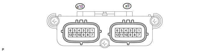
1. CHECK OCCUPANT CLASSIFICATION ECU
|
Terminal No. (Symbol) |
Wiring Color |
Terminal Description |
Condition |
Specified Condition |
|---|---|---|---|---|
|
a9-1 (+B) - a9-3 (GND) |
W - W-B |
Battery power supply |
Always |
11 to 14 V |
|
a9-2 (DIA) - a9-3 (GND) |
GR - W-B |
Diagnosis (DLC3) |
Ignition switch ON |
Pulse generation |
|
a9-3 (GND) - Body ground |
W-B - Body ground |
Ground |
Always |
Below 1 V |
|
a9-4 (FSR-) - a9-3 (GND) |
LG - W-B |
Center airbag sensor assembly communication line |
Always |
Below 1 V |
|
a9-5 (BGND) - a9-3 (GND) |
P - W-B |
Front passenger side buckle switch ground line |
Always |
Below 1 V |
|
a9-7 (IG2) - a9-3 (GND) |
B - W-B |
Ignition switch power supply |
Ignition switch ON |
11 to 14 V |
|
a9-8 (FSR+) - a9-4 (FSR- ) |
L - LG |
Center airbag sensor assembly communication line |
Ignition switch ON |
Pulse generation |
|
a9-9 (BSW) - a9-5 (BGND) |
G - P |
Front passenger side buckle switch line |
Always |
Pulse generation |
|
a10-1 (SGD1) - a9-3 (GND) |
G - W-B |
Front occupant classification sensor LH ground line |
Always |
Below 1 V |
|
a10-2 (SGD2) - a9-3 (GND) |
LG - W-B |
Front occupant classification sensor RH ground line |
Always |
Below 1 V |
|
a10-3 (SGD3) - a9-3 (GND) |
W - W-B |
Rear occupant classification sensor LH ground line |
Always |
Below 1 V |
|
a10-4 (SGD4) - a9-3 (GND) |
BR - W-B |
Rear occupant classification sensor RH ground line |
Always |
Below 1 V |
|
a10-11 (SVC1) - a10-1 (SGD1) |
R - G |
Front occupant classification sensor LH power supply line |
Ignition switch ON, load applied to front occupant classification sensor LH |
4.9 to 5.1 V |
|
a10-12 (SVC2) - a10-2 (SGD2) |
W - LG |
Front occupant classification sensor RH power supply line |
Ignition switch ON, load applied to front occupant classification sensor RH |
4.9 to 5.1 V |
|
a10-5 (SVC3) - a10-3 (SGD3) |
GR - W |
Rear occupant classification sensor LH signal line |
Ignition switch ON, load applied to rear occupant classification sensor LH |
4.9 to 5.1 V |
|
a10-6 (SVC4) - a10-4 (SGD4) |
V - BR |
Rear occupant classification sensor RH signal line |
Ignition switch ON, load applied to rear occupant classification sensor RH |
4.9 to 5.1 V |
|
a10-7 (SIG1) - a10-1 (SGD1) |
P - G |
Front occupant classification sensor LH signal line |
Ignition switch ON, load applied to front occupant classification sensor LH |
0 to 5.1 V |
|
a10-8 (SIG2) - a10-2 (SGD2) |
L - LG |
Front occupant classification sensor RH signal line |
Ignition switch ON, load applied to front occupant classification sensor RH |
0 to 5.1 V |
|
a10-9 (SIG3) - a10-3 (SGD3) |
SB - W |
Rear occupant classification sensor LH power supply line |
Ignition switch ON, load applied to rear occupant classification sensor LH |
0 to 5.1 V |
|
a10-10 (SIG4) - a10-4 (SGD4) |
B - BR |
Rear occupant classification sensor RH power supply line |
Ignition switch ON, load applied to rear occupant classification sensor RH |
0 to 5.1 V |
 Problem Symptoms Table
PROBLEM SYMPTOMS TABLE
HINT:
Use the table below to help determine the cause of problem symptoms.
If multiple suspected areas are listed, the potential causes of the symptoms
are lis ...
 Data List / Active Test
DATA LIST / ACTIVE TEST
NOTICE:
In the table below, the values listed under "Normal Condition" are reference
values. Do not depend solely on these reference values when deciding whether ...
Other materials about Toyota 4Runner:
Air Conditioning Compressor Magnetic Clutch Circuit
DESCRIPTION
When the air conditioning amplifier assembly is turned on, a magnet clutch assembly
signal is sent from the MGC terminal of the air conditioning amplifier assembly.
Then, the A/C COMP relay turns on to operate the magnet clutch assembly.
WIRI ...
Telephone Microphone Error (B1572)
DESCRIPTION
This DTC is stored when the DCM (Telematics Transceiver) detects a malfunction
in the telephone microphone assembly circuit.
DTC Code
DTC Detection Condition
Trouble Area
B1572
Curren ...

0.0087