Toyota 4Runner: Terminals Of Ecu
TERMINALS OF ECU
1. CHECK ENGINE SWITCH

(a) Disconnect the F71 switch connector.
(b) Measure the resistance according to the value(s) in the table below.
|
Terminal No. (Symbol) |
Wiring Color |
Terminal Description |
Condition |
Specified Condition |
|---|---|---|---|---|
|
F71-8 (AGND) - Body ground |
GR - Body ground |
Ground |
Always |
Below 1 Ω |
|
F71-5 (GND) - Body ground |
W-B - Body ground |
Ground |
Always |
Below 1 Ω |
If the result is not as specified, there may be a malfunction on the wire harness side.
(c) Reconnect the F71 switch connector.
(d) Measure the voltage according to the value(s) in the table below.
|
Terminal No. (Symbol) |
Wiring Color |
Terminal Description |
Condition |
Specified Condition |
|---|---|---|---|---|
|
F71-9 (TXCT) - F71-8 (AGND) |
W - GR |
Key code output signal |
Engine switch off, 30 seconds or more after door opened or closed and brake pedal not depressed |
Below 1 V |
|
F71-9 (TXCT) - F71-8 (AGND) |
W - GR |
Key code output signal |
Engine switch off, key not in cabin and 30 seconds or less after engine switch pushed |
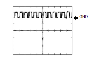
Pulse generation (see waveform 1) |
|
F71-10 (CODE) - F71-8 (AGND) |
V - GR |
Demodulated signal of key code data |
Engine switch off, 30 seconds or more after door opened or closed and brake pedal not depressed |
Below 1 V |
|
F71-10 (CODE) - F71-8 (AGND) |
V - GR |
Demodulated signal of key code data |
Engine switch off, key held against engine switch and engine switch pushed* |
Pulse generation (see waveform 2) |
|
F71-11 (SWIL) - F71-5 (GND) |
SB - W-B |
Illumination signal |
Engine switch off, light control rheostat fully turned upward and Light control switch off → tail |
Below 2 V → 9 to 14 V |
|
F71-14 (VC5) - F71-8 (AGND) |
P - GR |
Power supply |
Engine switch off, 30 seconds or more after door opened or closed and brake pedal not depressed |
Below 1 V |
|
F71-14 (VC5) - F71-8 (AGND) |
P - GR |
Power supply |
Engine switch off, key not in cabin and 30 seconds or less after engine switch pushed |
Pulse generation (see waveform 3) |
HINT:
*: Remove the key battery before performing this inspection.
If the result is not as specified, the engine switch may have a malfunction.
(e) Inspect using an oscilloscope.
(1) Waveform 1 (Reference)
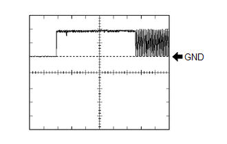 Measurement Condition
|
Item |
Content |
|---|---|
|
Tester Connection |
F71-9 (TXCT) - F71-8 (AGND) |
|
Tool Setting |
2 V/DIV., 20 ms./DIV. |
|
Condition |
Engine switch off, key not in cabin and 30 seconds or less after engine switch pushed |
(2) Waveform 2 (Reference)
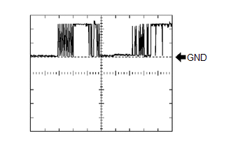 Measurement Condition
|
Item |
Content |
|---|---|
|
Tester Connection |
F71-10 (CODE) - F71-8 (AGND) |
|
Tool Setting |
2 V/DIV., 20 ms./DIV. |
|
Condition |
Engine switch off, key held against engine switch and engine switch pushed* |
HINT:
*: Remove the key battery before performing this inspection.
(3) Waveform 3 (Reference)
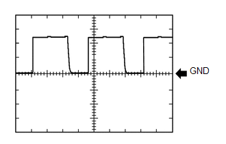 Measurement Condition
|
Item |
Content |
|---|---|
|
Tester Connection |
F71-14 (VC5) - F71-8 (AGND) |
|
Tool Setting |
2 V/DIV., 20 ms./DIV. |
|
Condition |
Engine switch off, key not in cabin and 30 seconds or less after engine switch pushed |
2. CHECK CERTIFICATION ECU
.png)
(a) Disconnect the F79 ECU connector.
(b) Measure the resistance and voltage according to the value(s) in the table below.
|
Terminal No. (Symbol) |
Wiring Color |
Terminal Description |
Condition |
Specified Condition |
|---|---|---|---|---|
|
F79-1 (+B) - F79-15 (E) |
V - W-B |
+B power supply |
Always |
11 to 14 V |
|
F79-17 (CUTB) - F79-15 (E) |
L - W-B |
+B power supply |
Always |
11 to 14 V |
|
F79-16 (IG) - F79-15 (E) |
W - W-B |
Ignition power supply |
Engine switch off → on (IG) |
Below 1 V → 11 to 14 V |
|
F79-15 (E) - Body ground |
W-B - Body ground |
Ground |
Always |
Below 1 Ω |
If the result is not as specified, there may be a malfunction on the wire harness side.
(c) Reconnect the F79 ECU connector.
(d) Measure the resistance and voltage according to the value(s) in the table below.
|
Terminal No. (Symbol) |
Wiring Color |
Terminal Description |
Condition |
Specified Condition |
|---|---|---|---|---|
|
F79-2 (IND) - F79-15 (E) |
L - W-B |
Security indicator output |
Engine switch off → on (IG) |
Pulse generation → Below 2 V |
|
F79-11 (SWIL) - F79-36 (AGND) |
SB - GR |
Illumination signal |
Engine switch off, light control rheostat fully turned upward and Light control switch off |
Below 2 V |
|
F79-11 (SWIL) - F79-36 (AGND) |
SB - GR |
Illumination signal |
Engine switch off, light control rheostat fully turned upward and Light control switch tail |
9 to 14 V |
|
F79-12 (TXCT) - F79-36 (AGND) |
W - GR |
Engine switch TXCT output |
Engine switch off, 30 seconds or more after door opened or closed and brake pedal not depressed |
Below 1 V |
|
F79-12 (TXCT) - F79-36 (AGND) |
W - GR |
Engine switch TXCT output |
Engine switch off, key not in cabin and 30 seconds or less after engine switch pushed |
Pulse generation (see waveform 1) |
|
F79-13 (CODE) - F79-36 (AGND) |
V - GR |
Engine switch CODE input |
Engine switch off, 30 seconds or more after door opened or closed and brake pedal not depressed |
Below 1 V |
|
F79-13 (CODE) - F79-36 (AGND) |
V - GR |
Engine switch CODE input |
Engine switch off, key held against engine switch and engine switch pushed* |
Pulse generation (see waveform 2) |
|
F79-28 (VC5) - F79-36 (AGND) |
P - GR |
Engine switch power supply |
Engine switch off, 30 seconds or more after door opened or closed and brake pedal not depressed |
Below 1 V |
|
F79-28 (VC5) - F79-36 (AGND) |
P - GR |
Engine switch power supply |
Engine switch off, key not in cabin and 30 seconds or less after engine switch pushed |
Pulse generation (see waveform 3) |
|
F79-36 (AGND) - Body ground |
GR - Body ground |
Engine switch ground |
Always |
Below 1 Ω |
HINT:
*: Remove the key battery before performing this inspection.
If the result is not as specified, the certification ECU may have a malfunction.
(e) Inspect using an oscilloscope.
(1) Waveform 1 (Reference)
Measurement Condition
|
Item |
Content |
|---|---|
|
Tester Connection |
F79-12 (TXCT) - F79-36 (AGND) |
|
Tool Setting |
2 V/DIV., 20 ms./DIV. |
|
Condition |
Engine switch off, key not in cabin and 30 seconds or less after engine switch pushed |
(2) Waveform 2 (Reference)
Measurement Condition
|
Item |
Content |
|---|---|
|
Tester Connection |
F79-13 (CODE) - F79-36 (AGND) |
|
Tool Setting |
2 V/DIV., 20 ms./DIV. |
|
Condition |
Engine switch off, key held against engine switch and engine switch pushed* |
HINT:
*: Remove the key battery before performing this inspection.
(3) Waveform 3 (Reference)
Measurement Condition
|
Item |
Content |
|---|---|
|
Tester Connection |
F79-28 (VC5) - F79-36 (AGND) |
|
Tool Setting |
2 V/DIV., 20 ms./DIV. |
|
Condition |
Engine switch off, key not in cabin and 30 seconds or less after engine switch pushed |
3. CHECK ID CODE BOX

(a) Disconnect the F72 box connector.
(b) Measure the resistance and voltage according to the value(s) in the table below.
|
Terminal No. (Symbol) |
Wiring Color |
Terminal Description |
Condition |
Specified Condition |
|---|---|---|---|---|
|
F72-1 (+B) - F72-8 (GND) |
V - W-B |
+B power supply |
Always |
11 to 14 V |
|
F72-8 (GND) - Body ground |
W-B - Body ground |
Ground |
Always |
Below 1 Ω |
If the result is not as specified, there may be a malfunction on the wire harness side.
(c) Reconnect the F72 box connector.
(d) Measure the voltage according to the value(s) in the table below.
|
Terminal No. (Symbol) |
Wiring Color |
Terminal Description |
Condition |
Specified Condition |
|---|---|---|---|---|
|
F72-5 (EFII) - F72-8 (GND) |
SB - W-B |
ECM input signal |
Within 3 seconds after starter operates and initial combustion occurs, or within 3 seconds after engine switch first turned on (IG) after battery disconnected and connected |
11 to 14 V → Pulse generation (see waveform 1) |
|
F72-6 (EFIO) - F72-8 (GND) |
W - W-B |
ECM output signal |
Engine switch off → on (IG) |
11 to 14 V → Pulse generation (see waveform 2) |
If the result is not as specified, the ID code box may have a malfunction.
(e) Inspect using an oscilloscope.
(1) Waveform 1 (Reference)
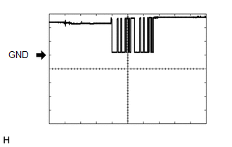 Measurement Condition
|
Item |
Content |
|---|---|
|
Tester Connection |
F72-5 (EFII) - F72-8 (GND) |
|
Tool Setting |
5 V/DIV., 500 ms./DIV. |
|
Condition |
Within 3 seconds after starter operates and initial combustion occurs, or within 3 seconds after engine switch first turned on (IG) after battery disconnected and connected |
(2) Waveform 2 (Reference)
 Measurement Condition
|
Item |
Content |
|---|---|
|
Tester Connection |
F72-6 (EFIO) - F72-8 (GND) |
|
Tool Setting |
10 V/DIV., 100 ms./DIV. |
|
Condition |
Engine switch on (IG) |
4. CHECK STEERING LOCK ACTUATOR ASSEMBLY (STEERING LOCK ECU)
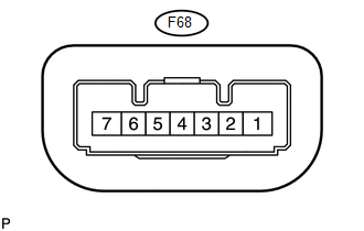
(a) Disconnect the F68 ECU connector.
(b) Measure the voltage and resistance according to the value(s) in the table below.
|
Terminal No. (Symbol) |
Wiring Color |
Terminal Description |
Condition |
Specified Condition |
|---|---|---|---|---|
|
F68-1 (GND) - Body ground |
W-B - Body ground |
Ground |
Always |
Below 1 Ω |
|
F68-6 (IG2) - F68-1 (GND) |
W - W-B |
IG2 signal input |
Engine switch off → on (IG) |
Below 1 V → 11 to 14 V |
|
F68-7 (B) - Body ground |
GR - Body ground |
Power source |
Always |
11 to 14 V |
If the result is not as specified, there may be a malfunction on the wire harness side.
5. CHECK POWER MANAGEMENT CONTROL ECU
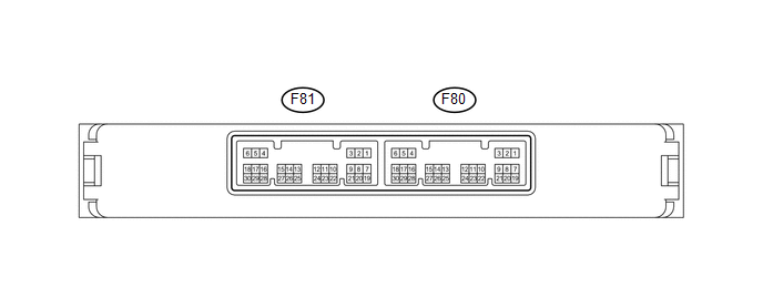
(a) Disconnect the F80 ECU connector.
(b) Measure the voltage and resistance according to the value(s) in the table below.
|
Terminal No. (Symbol) |
Wiring Color |
Terminal Description |
Condition |
Specified Condition |
|---|---|---|---|---|
|
F80-1 (AM22) - Body ground |
B - Body ground |
Battery power |
Always |
11 to 14 V |
|
F80-2 (AM21) - Body ground |
B - Body ground |
Battery power |
Always |
11 to 14 V |
|
F80-5 (GND2) - Body ground |
W-B - Body ground |
Ground |
Always |
Below 1 Ω |
|
F80-6 (GND) - Body ground |
W-B - Body ground |
Ground |
Always |
Below 1 Ω |
If the result is not as specified, there may be a malfunction on the wire harness side.
6. CHECK ECM
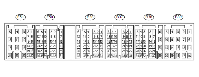
(a) Measure the voltage according to the value(s) in the table below.
|
Terminal No. (Symbol) |
Wiring Color |
Terminal Description |
Condition |
Specified Condition |
|---|---|---|---|---|
|
F50-20 (IMO) - Body ground |
SB - Body ground |
Transponder key ECU output signal |
Within 3 seconds after starter operates and initial combustion occurs, or within 3 seconds after engine switch first turned on (IG) after battery disconnected and connected |
11 to 14 V → Pulse generation (see waveform 1) |
|
F50-14 (IMI) - Body ground |
W - Body ground |
Transponder key ECU input signal |
Engine switch off → on (IG) |
11 to 14 V → Pulse generation (see waveform 2) |
If the result is not as specified, the ECM may have a malfunction.
(b) Inspect using an oscilloscope.
(1) Waveform 1 (Reference)
Measurement Condition
|
Item |
Content |
|---|---|
|
Tester Connection |
F50-20 (IMO) - Body ground |
|
Tool Setting |
5 V/DIV., 500 ms./DIV. |
|
Condition |
Within 3 seconds after starter operates and initial combustion occurs, or within 3 seconds after engine switch first turned on (IG) after battery disconnected and connected |
(2) Waveform 2 (Reference)
Measurement Condition
|
Item |
Content |
|---|---|
|
Tester Connection |
F50-14 (IMI) - Body ground |
|
Tool Setting |
10 V/DIV., 100 ms./DIV. |
|
Condition |
Engine switch on (IG) |
 Problem Symptoms Table
PROBLEM SYMPTOMS TABLE
HINT:
Use the table below to help determine the cause of problem symptoms.
If multiple suspected areas are listed, the potential causes of the symptoms
are lis ...
 Data List / Active Test
DATA LIST / ACTIVE TEST
1. READ DATA LIST
HINT:
Using the Techstream to read the Data List allows the values or states of switches,
sensors, actuators and other items to be read without removing ...
Other materials about Toyota 4Runner:
Portable Player cannot be Registered
CAUTION / NOTICE / HINT
HINT:
Some versions of "Bluetooth" compatible audio players may not function, or the
function may be limited using the radio and display receiver assembly, even if the
portable audio player itself can play files (See pag ...
AUTO LSD Indicator Light Remains ON
DESCRIPTION
During normal mode, pressing the VSC OFF switch for a short amount of time changes
vehicle to AUTO LSD mode.
WIRING DIAGRAM
CAUTION / NOTICE / HINT
NOTICE:
When replacing the master cylinder solenoid, perform calibration (See page
).
PR ...

0.0096