Toyota 4Runner: Dtc Check / Clear
DTC CHECK / CLEAR
1. DTC CHECK / CLEAR (when Using Techstream)
(a) Check for DTCs.
(1) Connect the Techstream to the DLC3.
(2) Turn the ignition switch to ON.
(3) Turn the Techstream on.
(4) Enter the following menus: Chassis / ABS/VSC/TRAC / Trouble Codes.
(5) Read the DTCs by following the prompts on the Techstream screen.
(b) Clear the DTCs.
(1) Connect the Techstream to the DLC3.
(2) Turn the ignition switch to ON.
(3) Turn the Techstream on.
(4) Enter the following menus: Chassis / ABS/VSC/TRAC / Trouble Codes.
(5) Operate the Techstream to clear the codes.
HINT:
Refer to the Techstream operator's manual for further details.
2. DTC CHECK / CLEAR (when Using SST Check Wire)
(a) Check for DTCs.
(1) Turn the ignition switch off.
(2) Using SST, connect terminals 13 (TC) and 4 (CG) of the DLC3.
SST: 09843-18040
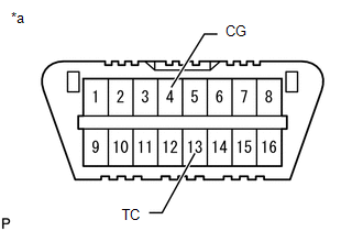 Text in Illustration
|
*a |
Front view of DLC3 |
(3) Turn the ignition switch to ON.
(4) Read the DTCs output from the ABS warning light and slip indicator light in the combination meter.
HINT:
- When the system is normal, the ABS warning light and slip indicator light blink at 0.25 seconds intervals (0.25 seconds on and 0.25 seconds off).
- When only 1 DTC is stored, the light outputs the same code after an interval of 4 seconds. Example: When DTC 21 is stored, the light blinks twice, turns off for 1.5 seconds, blinks once, turns off for 4 seconds, and then repeats this output pattern.
- When 2 or more DTCs are stored, the light outputs the codes with an interval of 2.5 seconds between each different code, and the output of all codes repeats after an interval of 4 seconds.
- If no code is output, inspect the TC and CG terminal circuit and the ABS warning light and slip indicator light circuits.
|
Trouble Area |
See Procedure |
|---|---|
|
TC and CG terminal circuit |
|
|
ABS warning light circuit (Remains on) |
|
|
ABS warning light circuit (Does not come on) |
|
|
Slip indicator light circuit (Remains on) |
|
|
Slip indicator light circuit (Does not come on) |
|
.gif)
(5) The codes are explained in the code table.
ABS DTC|
ABS Warning Light Display |
Techstream Display |
|---|---|
|
11 |
C0278 |
|
12 |
C0279 |
|
21 |
C0226 |
|
22 |
C0236 |
|
23 |
C0246 |
|
24 |
C0256 |
|
25 |
C1225 |
|
26 |
C1226 |
|
27 |
C1227 |
|
28 |
C1228 |
|
31 |
C1401 |
|
C1405 |
|
|
C1409 |
|
|
32 |
C1402 |
|
C1406 |
|
|
C1410 |
|
|
33 |
C1403 |
|
C1407 |
|
|
C1411 |
|
|
34 |
C1404 |
|
C1408 |
|
|
C1412 |
|
|
35 |
C1413 |
|
36 |
C1414 |
|
37 |
C1337 |
|
38 |
C1415 |
|
39 |
C1416 |
|
41 |
C1241 |
|
C1417 |
|
|
42 |
C1242 |
|
43 |
C1243 |
|
44 |
C1419 |
|
C1420 |
|
|
C1442 |
|
|
45 |
C1245 |
|
46 |
C1421 |
|
C1422 |
|
|
C1423 |
|
|
C1424 |
|
|
49 |
C1425 |
|
51 |
C1251 |
|
52 |
C1252 |
|
53 |
C1253 |
|
54 |
C1254 |
|
56 |
C1256 |
|
C1452 |
|
|
57 |
C1257 |
|
58 |
C1453 |
|
C1454 |
|
|
68 |
C1268 |
|
94 |
U0073 |
|
95 |
U0124 |
|
97 |
C1381 |
|
A1* |
U0114 |
- *: The light blinks 10 times, turns off for 1.5 seconds, and then blinks once.
|
Slip Indicator Light Display |
Techstream Display |
|---|---|
|
13 |
C120A |
|
31 |
C1432 |
|
C1433 |
|
|
C1434 |
|
|
32 |
C1232 |
|
34 |
C1435 |
|
C1436 |
|
|
C1443 |
|
|
36 |
C1210 |
|
39 |
C1336 |
|
43* |
- |
|
47 |
C1340 |
|
53 |
C1203 |
|
58 |
C1258 |
|
62 |
U0123 |
|
63 |
U0126 |
|
64 |
C1380 |
|
65 |
C1437 |
|
U0100 |
|
|
66 |
C1290 |
|
C1439 |
|
|
C1445 |
|
|
98 |
C1440 |
- *: This DTC is output when the VSC system detects a malfunction in the ABS.
(6) Disconnect terminals 13 (TC) and 4 (CG) of the DLC3.
If 2 or more DTCs are output at the same time, the DTCs are output in ascending order.
(b) Clear the DTCs.
(1) Turn the ignition switch off.
(2) Using SST, connect terminals 13 (TC) and 4 (CG) of the DLC3.
SST: 09843-18040
Text in Illustration
|
*a |
Front view of DLC3 |
(3) Turn the ignition switch to ON.
(4) Clear the DTCs stored in the ECU by depressing the brake pedal 8 times or more within 5 seconds.
(5) Check that the ABS warning light and slip indicator light blink at 0.25 second intervals (0.25 seconds on and 0.25 seconds off).
(6) Remove SST from the terminals of the DLC3.
3. END OF DTC CHECK/CLEAR
(a) Turn the ignition switch to ON.
(b) Check that the ABS warning light and slip indicator light go off within approximately 3 seconds.
 Terminals Of Ecu
TERMINALS OF ECU
1. TERMINALS OF ECU
Text in Illustration
*a
Component without harness connected
(Skid Control ECU)
-
-
Terminal ...
 Freeze Frame Data
FREEZE FRAME DATA
1. FREEZE FRAME DATA
(a) Whenever a DTC is stored, the skid control ECU stores the current vehicle
(sensor) state as freeze frame data.
(b) The skid control ECU stores the numbe ...
Other materials about Toyota 4Runner:
Disassembly
DISASSEMBLY
PROCEDURE
1. REMOVE NO. 1 HEATER TO REGISTER DUCT
(a) Remove the 4 screws and No. 1 heater to register duct.
2. REMOVE NO. 2 HEATER TO REGISTER DUCT
(a) Remove the 4 screws and No ...
Open Circuit in Transfer 4WD Position Switch Circuit (C1258,C1340)
DESCRIPTION
DTC Code
DTC Detection Condition
Trouble Area
C1258*1
C1340*2
An open circuit is detected in the EXI circuit of the skid control ECU.
Harness or connector
...

0.0092