Toyota 4Runner: Torque Converter Clutch Pressure Control Solenoid Control Circuit Electrical (Shift Solenoid Valve SLU) (P2759)
DESCRIPTION
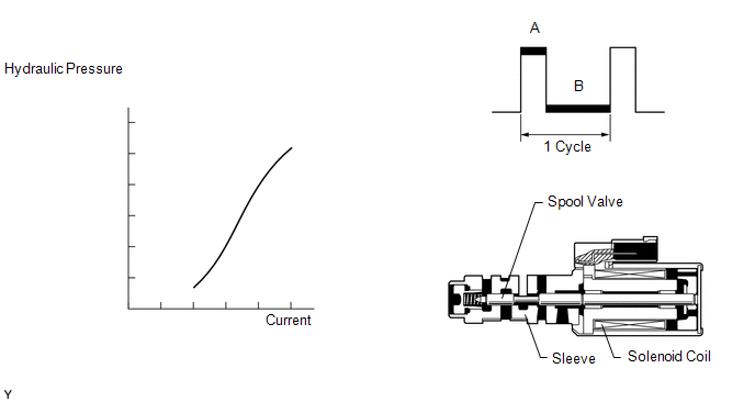
The amount of current flow to the solenoid is controlled by the duty ratio* of the ECM output signal. During the lock-up operation, if the duty ratio increases, the lock-up hydraulic pressure increases.
HINT:
*: The duty ratio is the ratio of the current ON time (A) to the total of the current ON and OFF time (A + B). Duty Ratio (%) = A / (A + B) x 100
|
DTC Code |
DTC Detection Condition |
Trouble Area |
|---|---|---|
|
P2759 |
Open or short is detected in the shift solenoid valve SLU circuit for 1 sec. or more while driving (1-trip detection logic). |
|
MONITOR DESCRIPTION
When an open or short in the shift solenoid valve (SLU) circuit is detected, the ECM determines there is a malfunction. The ECM will turn on the MIL and store this DTC.
MONITOR STRATEGY
|
Related DTCs |
P2759: Shift solenoid valve SLU/Range check |
|
Required sensors/Components |
Shift solenoid valve SLU |
|
Frequency of operation |
Continuous |
|
Duration |
1 sec. |
|
MIL operation |
Immediate |
|
Sequence of operation |
None |
TYPICAL ENABLING CONDITIONS
All|
The monitor will run whenever the following DTCs are not stored |
None |
|
Battery voltage |
8 V or higher |
|
Ignition switch |
ON |
|
Starter |
OFF |
|
Solenoid current cut status |
Not cut |
|
Battery voltage |
11 V or higher |
|
Target duty cycle |
19% or more |
|
Target duty cycle |
100% |
TYPICAL MALFUNCTION THRESHOLDS
|
Solenoid status from solenoid driver MIC |
Failure |
COMPONENT OPERATING RANGE
|
Output signal duty |
Less than 100% |
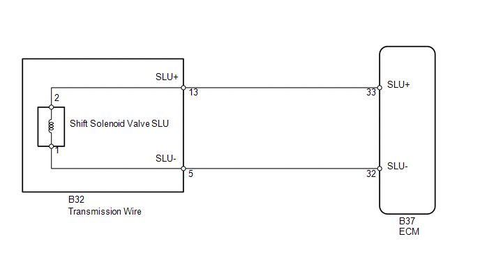
WIRING DIAGRAM
CAUTION / NOTICE / HINT
NOTICE:
Perform the universal trip to clear permanent DTCs (See page
.gif) ).
).
PROCEDURE
|
1. |
INSPECT TRANSMISSION WIRE (SHIFT SOLENOID VALVE SLU) |
|
(a) Disconnect the B32 transmission wire connector. |
|
(b) Measure the resistance according to the value(s) in the table below.
Standard Resistance:
|
Tester Connection |
Condition |
Specified Condition |
|---|---|---|
|
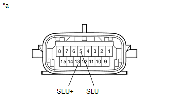
13 (SLU+) - 5 (SLU-) |
20°C (68°F) |
5.0 to 5.6 Ω |
|
13 (SLU+) - Body ground |
Always |
10 kΩ or higher |
|
5 (SLU-) - Body ground |
Always |
10 kΩ or higher |
|
*a |
Component without harness connected (Transmission Wire) |
| NG | .gif) |
GO TO STEP 3 |
|
.gif)
|
2. |
CHECK HARNESS AND CONNECTOR (TRANSMISSION WIRE - ECM) |
|
(a) Disconnect the B37 ECM connector. |
|
(b) Measure the resistance according to the value(s) in the table below.
Standard Resistance:
|
Tester Connection |
Condition |
Specified Condition |
|---|---|---|
|
B37-33 (SLU+) - B37-32 (SLU-) |
20°C (68°F) |
5.0 to 5.6 Ω |
|
B37-33 (SLU+) - Body ground |
Always |
10 kΩ or higher |
|
B37-32 (SLU-) - Body ground |
Always |
10 kΩ or higher |
|
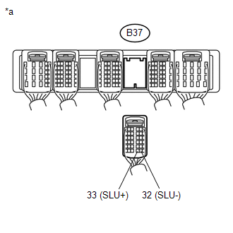
*a |
Rear view of wire harness connector (to ECM) |
| OK | |
REPLACE ECM |
| NG | |
REPAIR OR REPLACE HARNESS OR CONNECTOR |
|
3. |
INSPECT SHIFT SOLENOID VALVE SLU |
| OK | |
REPAIR OR REPLACE TRANSMISSION WIRE |
| NG | |
REPLACE SHIFT SOLENOID VALVE SLU |
 Diagnostic Trouble Code Chart
DIAGNOSTIC TROUBLE CODE CHART
HINT:
If a DTC is output during the DTC check, check the parts listed in the
table below and proceed to the "See page" given.
*1: "Comes ...
 Torque Converter Clutch Pressure Control Solenoid Performance (Shift Solenoid
Valve SLU) (P2757)
Torque Converter Clutch Pressure Control Solenoid Performance (Shift Solenoid
Valve SLU) (P2757)
DESCRIPTION
The ECM uses the signals from the throttle position sensor, air-flow meter, turbine
(input) speed sensor, output speed sensor and crankshaft position sensor to monitor
the engagement ...
Other materials about Toyota 4Runner:
Reassembly
REASSEMBLY
PROCEDURE
1. INSTALL FOG LIGHT ASSEMBLY LH
2. INSTALL FOG LIGHT ASSEMBLY RH
HINT:
Use the same procedure as for the LH side.
3. INSTALL FRONT BUMPER MOULDING SUB-ASSEMBLY
(a) Attach the 4 claws and 12 guides to install the front bumper mou ...
AUTO LSD system (2WD models)
The AUTO LSD system aids traction by using the traction control system to
control engine performance and braking when one of the rear wheels begins to
spin.
The system should be used only when wheel spinning occurs in a ditch or rough
surface.
System o ...
0.0097