Toyota 4Runner: Inspection
INSPECTION
PROCEDURE
1. INSPECT DIFFERENTIAL LOCK SYSTEM
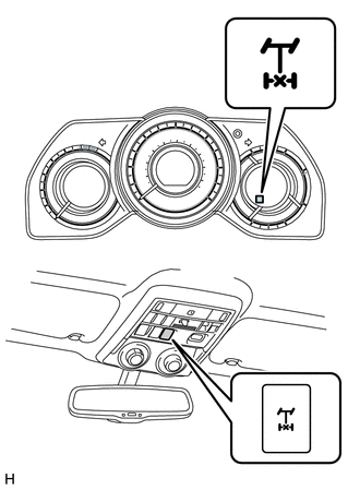
(a) Inspect the indicator light.
(1) Check that the indicator light lights up approximately 1 second after the ignition switch is turned ON.
(b) Inspect the differential lock operation.
(1) Jack up the vehicle and start the engine.
(2) Set the transfer to L4.
(3) When the differential lock control switch is set to the ON position, check that the indicator light turns on. Differential lock is applied to the rear wheels at this time.
HINT:
If the gears of the differential lock system are not engaged, the indicator light continues blinking, so rotate the tires to engage the gears.
(4) When the differential lock control switch is in the OFF position, check that the indicator light goes off. The rear differential lock is released at this time.
(5) Stop the engine and lower the vehicle.
2. INSPECT FOUR WHEEL DRIVE CONTROL ECU (POWER SUPPLY)
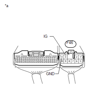
(a) Check the harness and connector (ECU - battery and body ground).
(1) Measure the voltage according to the value(s) in the table below.
Standard Voltage:
|
Tester Connection |
Switch Condition |
Specified Condition |
|---|---|---|
|
F46-3 (IG) - Body ground |
Ignition switch ON |
11 to 14 V |
|
*a |
Component with harness connected (Four Wheel Drive Control ECU) |
If the result is not as specified, inspect the harness or connector. If the harness
is malfunctioning, repair or replace the harness connector or 4WD fuse. If the harness
and connector are normal, replace the four wheel drive control ECU (See page
.gif) ).
).
(2) Measure the resistance according to the value(s) in the table below.
Standard Resistance:
|
Tester Connection |
Condition |
Specified Condition |
|---|---|---|
|
F46-10 (GND) - Body ground |
Always |
Below 1 Ω |
If the result is not as specified, repair or replace the harness or connector.
3. INSPECT DIFFERENTIAL LOCK SWITCH
(a) Check the harness and connector (differential lock switch - ECU).
(1) Disconnect the F47 ECU connector.
(2) Disconnect the U5 switch connector.
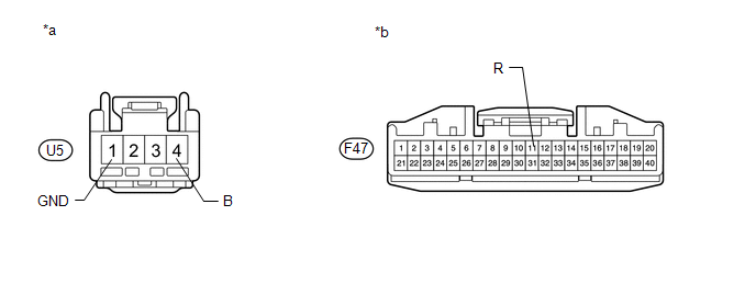
(3) Measure the resistance according to the value(s) in the table below.
 Text in Illustration
|
*a |
Front view of wire harness connector (to Differential Lock Switch) |
*b |
Front view of wire harness connector (to Four Wheel Drive Control ECU) |
Standard Resistance:
|
Tester Connection |
Condition |
Specified Condition |
|---|---|---|
|
U5-4 (B) - F47-11 (R) |
Always |
Below 1 Ω |
|
U5-1 (GND) - Body ground |
Always |
Below 1 Ω |
|
U5-1 (GND) - F47-11 (R) |
Always |
100 kΩ or higher |
If the result is not specified, repair or replace the harness or connector.
(b) Check the differential lock switch.
(1) Turn the ignition switch off.
(2) Connect the U5 switch connector.
(3) Connect the F47 ECU connector.
|
(4) Measure the resistance according to the value(s) in the table below. Standard Voltage:
|
|
4. INSPECT REAR DIFFERENTIAL LOCK ACTUATOR
(a) Check the harness and connector (rear differential lock actuator - ECU).
(1) Disconnect the D2 differential lock actuator connector.
(2) Disconnect the F47 and F46 ECU connectors.
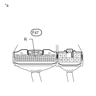
(3) Measure the resistance according to the value(s) in the table below.
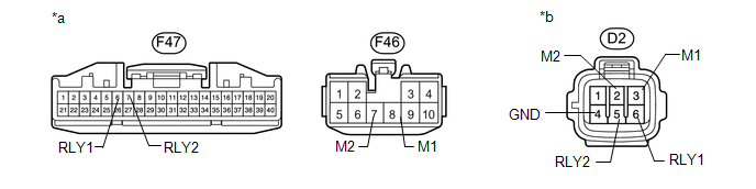 Text in Illustration
|
*a |
Front view of wire harness connector (to Four Wheel Drive Control ECU) |
*b |
Front view of wire harness connector (to Differential Lock Actuator) |
Standard Resistance:
|
Tester Connection |
Condition |
Specified Condition |
|---|---|---|
|
F47-7 (RLY2) - D2-5 (RLY2) |
Always |
Below 1 Ω |
|
F47-7 (RLY2) - Body ground |
Always |
100 kΩ or higher |
|
F47-6 (RLY1) - D2-6 (RLY1) |
Always |
Below 1 Ω |
|
F47-6 (RLY1) - Body ground |
Always |
100 kΩ or higher |
|
F46-7 (M2) - D2-2 (M2) |
Always |
Below 1 Ω |
|
F46-7 (M2) - Body ground |
Always |
100 kΩ or higher |
|
F46-8 (M1) - D2-3 (M1) |
Always |
Below 1 Ω |
|
F46-8 (M1) - Body Ground |
Always |
100 kΩ or higher |
|
D2-4 (GND) - Body Ground |
Always |
Below 1 Ω |
(b) Check the free to lock switch.
(1) Connect lines via a relay as shown in the illustration and check that the actuator fork moves from the free to the lock position.
NOTICE:
- Make sure to perform this inspection with the actuator removed from the vehicle. If this inspection is performed with the actuator installed to the vehicle, the actuator will be damaged.
- When inspecting the actuator, make sure to operate it with the lines connected via a relay. If the lines are not connected via a relay and battery voltage is directly applied to the actuator, the actuator will be damaged.
HINT:
When performing the operation described above, use the stop LP relay.
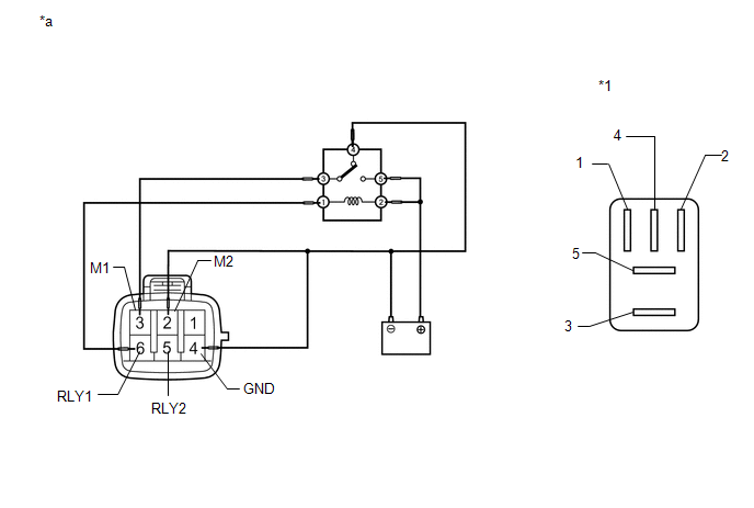 Text in Illustration
|
*1 |
Stop LP Relay |
- |
- |
|
*a |
Front view of wire harness connector (to Differential Lock Actuator) |
- |
- |
(2) After the free to lock switch is complete, check the limit switch.
Measure the resistance according to the value(s) in the table below.
Standard Resistance:
|
Tester Connection |
Condition |
Specified Condition |
|---|---|---|
|
5 (RLY2) - 4 (GND) |
After free to lock switch is complete |
Below 12.5 Ω |
|
6 (RLY1) - 4 (GND) |
After free to lock switch is complete |
500 kΩ or higher |
If the result is not as specified, replace the differential lock shift actuator assembly.
(c) Check the lock to free switch.
(1) Connect lines via a relay as shown in the illustration and check that the actuator fork moves from the lock to the free position.
NOTICE:
- Make sure to perform this inspection with the actuator removed from the vehicle. If this inspection is performed with the actuator installed to the vehicle, the actuator will be damaged.
- When inspecting the actuator, make sure to operate it with the lines connected via a relay. If the lines are not connected via a relay and battery voltage is directly applied to the actuator, the actuator will be damaged.
HINT:
When performing the operation described above, use the stop LP relay.
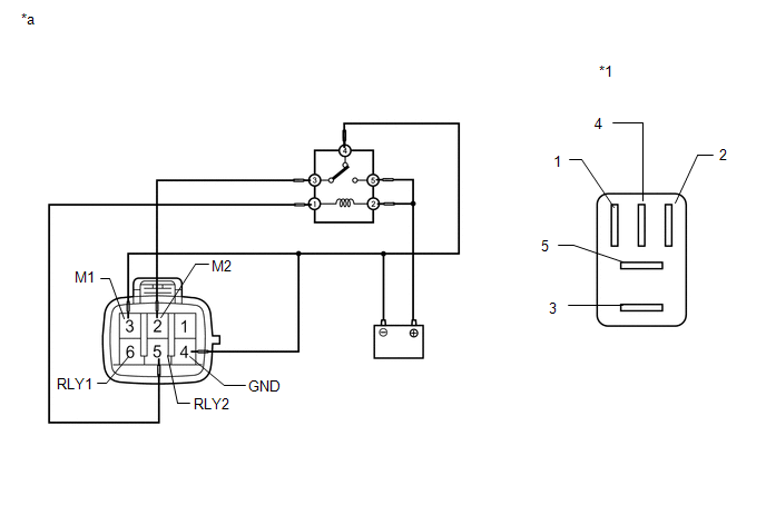 Text in Illustration
|
*1 |
Stop LP Relay |
- |
- |
|
*a |
Front view of wire harness connector (to Differential Lock Actuator) |
- |
- |
(2) After the lock to free switch is complete, check the limit switch.
Measure the resistance according to the value(s) in the table below.
Standard Resistance:
|
Tester Connection |
Condition |
Specified Condition |
|---|---|---|
|
5 (RLY2) - 4 (GND) |
After lock to free switch is complete |
500 kΩ or higher |
|
6 (RLY1) - 4 (GND) |
After lock to free switch is complete |
Below 12.5 Ω |
If the result is not as specified, replace the differential lock shift actuator assembly.
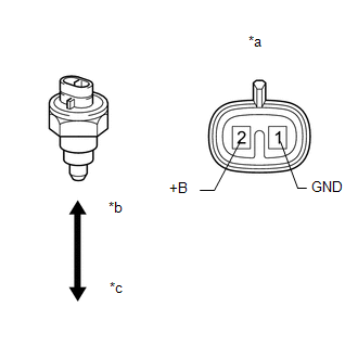
5. INSPECT DIFFERENTIAL LOCK POSITION SWITCH
(a) Inspect the rear differential lock position switch.
(1) Remove the rear differential lock position switch (See page
).
|
(2) Measure the resistance according to the value(s) in the table below. Standard Resistance:
If the result is not as specified, replace the rear differential lock position switch. |
|
(b) Check the harness and connector (ECU - differential lock position switch).
(1) Disconnect the D3 differential lock position switch connector.
(2) Disconnect the F47 ECU connector.
(3) Measure the resistance according to the value(s) in the table below.
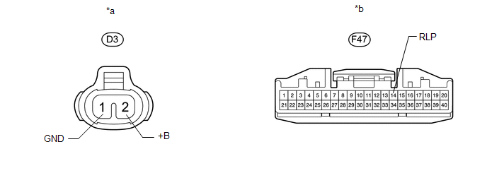 Text in Illustration
|
*a |
Component without harness connected (Rear Differential Lock Position Switch) |
*b |
Component without harness connected (Four Wheel Drive Control ECU) |
Standard Resistance:
|
Tester Connection |
Condition |
Specified Condition |
|---|---|---|
|
F47-14 (RLP) - D3-2 (+B) |
Always |
Below 1 Ω |
|
F47-14 (RLP) - Body ground |
Always |
100 kΩ or higher |
|
D3-1 (GND) - Body ground |
Always |
Below 1 Ω |
If the result is not as specified, repair or replace the harness or connector.
6. INSPECT AUTOMATIC DISCONNECTING DIFFERENTIAL ACTUATOR
NOTICE:
When inspecting the actuator, make sure to operate it with the lines connected via a relay. If the lines are not connected via a relay and battery voltage is directly applied to the actuator, the actuator will be damaged.
HINT:
When inspecting the operation described above, use the stop LP relay.
(a) Check the free to lock switch.
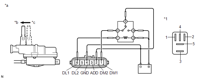 Text in Illustration
|
*1 |
Stop LP Relay |
- |
- |
|
*a |
Component without harness connected (A.D.D. Actuator Connector) |
*b |
Lock |
|
*c |
Free |
- |
- |
(1) Connect lines via a relay as shown in the illustration and check that the actuator fork moves from the free to the lock position.
(2) After the free to lock switch is complete, inspect the A.D.D. detection switch and limit switch.
Standard Resistance:
|
Tester Connection |
Condition |
Specified Condition |
|---|---|---|
|
3 (ADD) - 4 (GND) |
After free to lock switch is complete |
Below 12.5 Ω |
|
5 (DL2) - 4 (GND) |
Below 12.5 Ω |
|
|
6 (DL1) - 4 (GND) |
0.5 MΩ or higher |
If the result is not as specified, replace the A.D.D. actuator. If the A.D.D. actuator is normal, replace the four wheel drive control ECU.
(b) Check the lock to free switch.
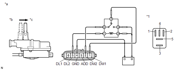 Text in Illustration
|
*1 |
Stop LP Relay |
- |
- |
|
*a |
Component without harness connected (A.D.D Actuator Connector) |
*b |
Lock |
|
*c |
Free |
- |
- |
(1) Connect lines via a relay as shown in the illustration and check that the actuator fork moves from the lock to the free position.
(2) After the lock to free switch is complete, inspect the A.D.D. detection switch and limit switch.
Standard Resistance:
|
Tester Connection |
Condition |
Specified Condition |
|---|---|---|
|
3 (ADD) - 4 (GND) |
After lock to free switch is complete |
0.5 MΩ or higher |
|
5 (DL2) - 4 (GND) |
0.5 MΩ or higher |
|
|
6 (DL1) - 4 (GND) |
Below 12.5 Ω |
If the result is not as specified, replace the A.D.D. actuator. If the A.D.D. actuator is normal, replace the four wheel drive control ECU.
 Terminals Of Ecu
TERMINALS OF ECU
1. CHECK 4WD CONTROL ECU
(a) Measure the voltage and resistance according to the value(s) in the table
below.
Terminal No. (Symbol)
Wiring Color
...
 Front Axle Hub Bolt
Components
COMPONENTS
ILLUSTRATION
Replacement
REPLACEMENT
CAUTION / NOTICE / HINT
HINT:
Use the same procedure for the RH and LH sides.
The procedure listed below is for the ...
Other materials about Toyota 4Runner:
Sending Malfunction (Navigation to APGS) (U0073,U0140)
DESCRIPTION
These DTCs are stored when a malfunction occurs in the CAN communication circuit.
DTC No.
DTC Detection Condition
Trouble Area
U0073
CAN reception error
CAN communication sys ...
Reassembly
REASSEMBLY
CAUTION / NOTICE / HINT
HINT:
When installing the back door outside garnish seal, heat the back door outside
garnish surface using a heat light.
Standard:
Item
Temperature
Back Door Outside Garnish
...

0.0067