
Toyota 4Runner: Transfer Case Front Oil Seal
Components
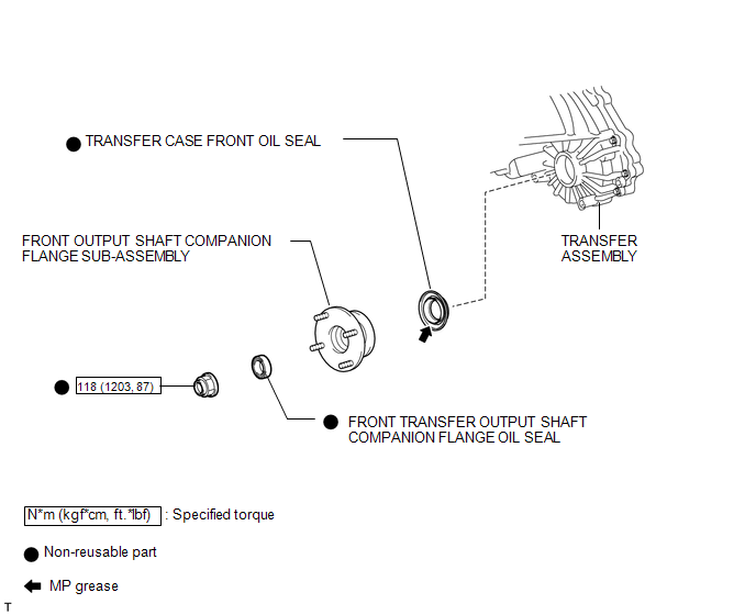
COMPONENTS
ILLUSTRATION
Replacement
REPLACEMENT
PROCEDURE
1. DRAIN TRANSFER OIL
.gif)
2. REMOVE FRONT PROPELLER SHAFT ASSEMBLY
(a) Remove the front propeller shaft (See page
).
3. REMOVE FRONT OUTPUT SHAFT COMPANION FLANGE SUB-ASSEMBLY
4. REMOVE FRONT TRANSFER OUTPUT SHAFT COMPANION FLANGE OIL SEAL
5. REMOVE TRANSFER CASE FRONT OIL SEAL
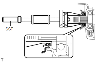
(a) Using SST, tap out the oil seal.
SST: 09308-00010
NOTICE:
Be careful not to damage the oil seal and case front contact surface.
6. INSTALL TRANSFER CASE FRONT OIL SEAL
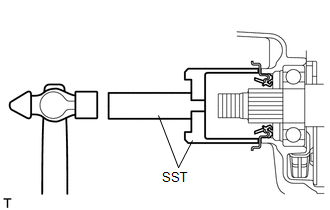
(a) Coat the lip of a new oil seal with MP grease.
(b) Using SST and a hammer, tap in the oil seal until its metal ring contacts the case.
SST: 09649-17010
SST: 09950-70010
09951-07100
7. INSTALL FRONT TRANSFER OUTPUT SHAFT COMPANION FLANGE OIL SEAL
8. INSTALL FRONT OUTPUT SHAFT COMPANION FLANGE SUB-ASSEMBLY
9. INSTALL FRONT PROPELLER SHAFT ASSEMBLY
(a) Install the front propeller shaft (See page
).
10. ADD TRANSFER OIL
11. CHECK FOR TRANSFER OIL LEAK
 Installation
INSTALLATION
PROCEDURE
1. INSTALL TRANSFER ASSEMBLY
(a) Install the transfer to the transmission.
(b) Install the 8 bolts.
Torque:
24 N·m {245 kgf·cm, 18 ft·lbf}
2. INSTALL AUTOMATIC TRANSM ...
 Transfer Case Rear Oil Seal
Components
COMPONENTS
ILLUSTRATION
Replacement
REPLACEMENT
PROCEDURE
1. DRAIN TRANSFER OIL
2. REMOVE REAR PROPELLER SHAFT ASSEMBLY
(a) Remove the rear propeller shaft (See page
).
...
Other materials about Toyota 4Runner:
Reassembly
REASSEMBLY
PROCEDURE
1. INSTALL TRANSFER POSITION SWITCH (for VF2BM)
2. INSTALL TRANSFER POSITION SWITCH (for VF4BM)
3. INSTALL NO. 2 BOX BOTTOM MAT (for 2WD)
(a) Attach the 4 claws to install the No. 2 box bottom mat.
4. INSTALL FRONT UPPER CONSOL ...
Removal
REMOVAL
PROCEDURE
1. DISCONNECT CABLE FROM NEGATIVE BATTERY TERMINAL
CAUTION:
Wait at least 90 seconds after disconnecting the cable from the negative (-)
battery terminal to disable the SRS system.
NOTICE:
When disconnecting the cable, some systems ne ...

0.026