
Toyota 4Runner: Yaw Rate And Acceleration Sensor
Components
COMPONENTS
ILLUSTRATION
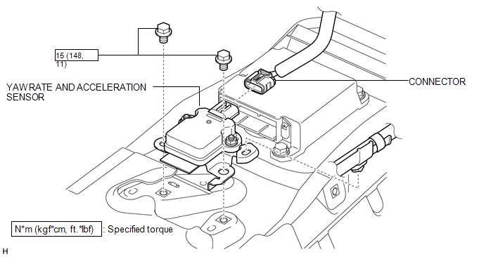
Removal
REMOVAL
PROCEDURE
1. DISCONNECT CABLE FROM NEGATIVE BATTERY TERMINAL
CAUTION:
Wait at least 90 seconds after disconnecting the cable from the negative (-) battery terminal to disable the SRS system.
NOTICE:
When disconnecting the cable, some systems need to be initialized after the cable
is reconnected (See page .gif) ).
).
2. REMOVE REAR CONSOLE BOX SUB-ASSEMBLY
(a) Remove the rear console box sub-assembly (See page
).
3. REMOVE YAW RATE AND ACCELERATION SENSOR
|
(a) Remove the 2 bolts and yaw rate and acceleration sensor. |
|
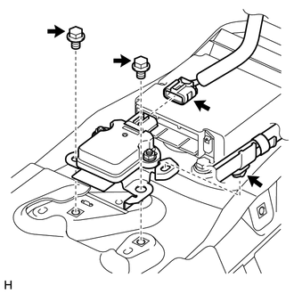
(b) Disconnect the connector, and then detach the clamp from the sensor bracket.
Inspection
INSPECTION
PROCEDURE
1. CHECK YAW RATE AND ACCELERATION SENSOR
(a) Check the yaw rate and acceleration sensor.
Under any of the following conditions, replace the sensor with a new one:
- The surface of the sensor is cracked, dented or chipped.
- The connector is scratched, cracked or damaged.
- The sensor has been dropped.
Installation
INSTALLATION
PROCEDURE
1. INSTALL YAW RATE AND ACCELERATION SENSOR
(a) Connect the connector, and then attach the clamp to the hole of the sensor bracket.
NOTICE:
Securely connect the connector.
(b) Install the yaw rate and acceleration sensor with the 2 bolts.
Torque:
15 N·m {148 kgf·cm, 11 ft·lbf}
NOTICE:
- If the sensor is dropped, replace it.
- Make sure the bracket rotation stopper touches the installation position.
- Make sure that the sensor is oriented correctly.
- When installing the sensor, make sure to avoid impacts to the sensor.
2. INSTALL REAR CONSOLE BOX SUB-ASSEMBLY
(a) Install the rear console box sub-assembly (See page
.gif) ).
).
3. CONNECT CABLE TO NEGATIVE BATTERY TERMINAL
NOTICE:
When disconnecting the cable, some systems need to be initialized after the cable
is reconnected (See page ).
4. PERFORM YAW RATE AND ACCELERATION SENSOR ZERO POINT CALIBRATION
(a) Perform yaw rate and acceleration sensor zero point calibration (See page
).
5. CHECK YAW RATE AND ACCELERATION SENSOR SIGNAL
(a) Check the yaw rate and acceleration sensor signal (See page
).
 Vsc Off Switch
Components
COMPONENTS
ILLUSTRATION
Removal
REMOVAL
PROCEDURE
1. REMOVE DRIVE MONITOR SWITCH
2. REMOVE MAP LIGHT ASSEMBLY
3. REMOVE VSC OFF SWITCH
(a) Disconnect the 2 c ...

Other materials about Toyota 4Runner:
Disassembly
DISASSEMBLY
PROCEDURE
1. REMOVE BACK DOOR OPENER SWITCH ASSEMBLY
2. REMOVE NO. 2 BACK DOOR OUTSIDE GARNISH
(a) Detach the 2 clips and No. 2 back door outside garnish.
3. REMOVE LICENSE PLATE LIGHT ASSEMBLY
4. REMOVE BACK DOOR OUTSIDE GARNISH SEAL ...
Horn
Components
COMPONENTS
ILLUSTRATION
Inspection
INSPECTION
PROCEDURE
1. INSPECT HIGH PITCHED HORN ASSEMBLY
(a) Apply battery voltage and check the operation of the horn according to the
table below.
OK:
Measurement Condition
...

0.0069