Toyota 4Runner: Vsc Off Switch
Components
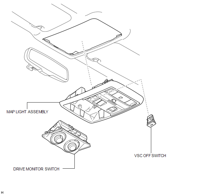
COMPONENTS
ILLUSTRATION
Removal
REMOVAL
PROCEDURE
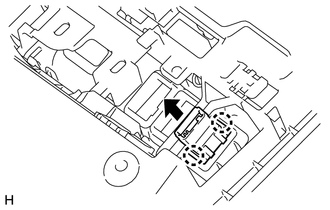
1. REMOVE DRIVE MONITOR SWITCH
.gif)
2. REMOVE MAP LIGHT ASSEMBLY
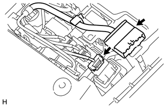
3. REMOVE VSC OFF SWITCH
|
(a) Disconnect the 2 connectors. |
|
|
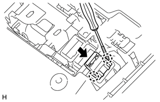
(b) Using a screwdriver, detach the 2 claws and remove the VSC OFF switch from the map light assembly. HINT: Tape the screwdriver tip before use. |
|
Inspection
INSPECTION
PROCEDURE
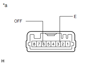
1. INSPECT VSC OFF SWITCH
|
(a) Measure the resistance according to the value(s) in the table below. Standard Resistance:
If the value is not as specified, replace the VSC OFF switch. |
|
Installation
INSTALLATION
PROCEDURE
1. INSTALL VSC OFF SWITCH
|
(a) Attach the 2 claws to install the VSC OFF switch to the map light assembly. |
|
(b) Connect the 2 connectors.
2. INSTALL MAP LIGHT ASSEMBLY
.gif)
3. INSTALL DRIVE MONITOR SWITCH
 TS and CG Terminal Circuit
DESCRIPTION
The signal check circuit detects trouble in the sensor or switch signal which
cannot be detected by the DTC check.
Connecting terminals TS and CG of the DLC3 starts the check.
WIRING ...
 Yaw Rate And Acceleration Sensor
Components
COMPONENTS
ILLUSTRATION
Removal
REMOVAL
PROCEDURE
1. DISCONNECT CABLE FROM NEGATIVE BATTERY TERMINAL
CAUTION:
Wait at least 90 seconds after disconnecting the cable from the n ...
Other materials about Toyota 4Runner:
Cursor or Map Rotates when Vehicle Stopped
PROCEDURE
1.
CHECK CONDITION
(a) Check with the customer if the vehicle has been turned by a turntable.
OK:
Vehicle has not been turned by a turntable.
HINT:
If the vehicle is turned on a turntable with ...
Installation
INSTALLATION
PROCEDURE
1. INSTALL BRAKE ACTUATOR BOLT CUSHION
(a) Install the 3 brake actuator bolt cushions to the brake actuator bracket.
2. INSTALL BRAKE ACTUATOR CASE COLLAR
(a) Install the 3 brake actuator case collars to the brake actuator bolt cush ...

0.0076