Toyota 4Runner: Disassembly
DISASSEMBLY
CAUTION / NOTICE / HINT
HINT:
- Use the same procedure for both the RH and LH sides.
- The procedure listed below is for the LH side.
PROCEDURE
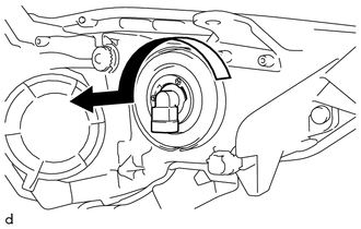
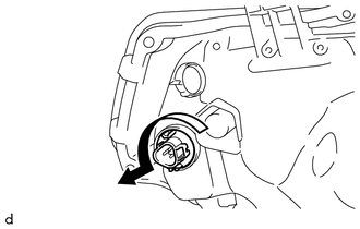
1. REMOVE NO. 1 HEADLIGHT BULB
|
(a) Turn the No. 1 headlight bulb in the direction indicated by the arrow and pull to remove it. |
|
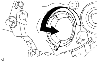
2. REMOVE HEADLIGHT SOCKET COVER
|
(a) Turn the headlight socket cover in the direction indicated by the arrow and pull to remove it. |
|
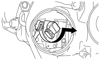
3. REMOVE NO. 2 HEADLIGHT BULB
(a) Disconnect the connector.
|
(b) Turn the No. 2 headlight bulb in the direction indicated by the arrow and pull to remove it. |
|
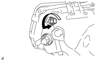
4. REMOVE FRONT SIDE MARKER LIGHT SOCKET
|
(a) Turn the socket in the direction indicated by the arrow and pull to remove the front side marker light socket with the front side marker light bulb. |
|
5. REMOVE FRONT SIDE MARKER LIGHT BULB
(a) Remove the front side marker light bulb from the front side marker light socket.
6. REMOVE FRONT TURN SIGNAL LIGHT SOCKET
|
(a) Turn the socket in the direction indicated by the arrow and pull to remove the front turn signal light socket with the front turn signal light bulb. |
|
7. REMOVE FRONT TURN SIGNAL LIGHT BULB
(a) Remove the front turn signal light bulb from the front turn signal light socket.
 Components
COMPONENTS
ILLUSTRATION
ILLUSTRATION
...
 Removal
REMOVAL
CAUTION / NOTICE / HINT
HINT:
Use the same procedure for both the RH and LH sides.
The procedure listed below is for the LH side.
PROCEDURE
1. REMOVE UPPER RADIATOR SUPP ...
Other materials about Toyota 4Runner:
Reassembly
REASSEMBLY
PROCEDURE
1. BEARING POSITION
Bearing and Race Diameter:
Mark
Front Race Diameter Inside/Outside
Thrust Bearing Diameter Inside/Outside
Rear Race Diameter Inside/Outside
A
...
AUTO LSD system (2WD models)
The AUTO LSD system aids traction by using the traction control system to
control engine performance and braking when one of the rear wheels begins to
spin.
The system should be used only when wheel spinning occurs in a ditch or rough
surface.
System o ...

0.0078